BMW M5 Forum and M6 Forums banner

Pixel fix replacement ribbon diy

60K views 20 replies 15 participants last post by  ger  
#1 ·
Yesterday I bit the bullet and decided to sort out the pixel problem on my dash.

My car is definitely out of warranty and has no 3rd party warranty either, so it was up to me to sort this out somehow. Obviously, it would have been nice to get a new one from the dealer, but I have a feeling that they would not have entertained the thought!

A couple of months ago I bought a repair kit off ebay for £26. It's the same guy as BMW LCD pixelhiba javítás, autóműszer autóelektronika diagnosztika. . The kit consisted of a replacement plastic ribbon to go from the circuit board to the LCD and an instruction pamphlet.

I didn't jump to it as I saw that the replacement ribbon had no adhesive at all. This worried me a bit as I knew that the oem ribbon is bonded at both ends. I thought about it and researched it for a while and it turns out that the ribbon does not need to be bonded to the circuit board (nor the LCD).

Back to yesterday:
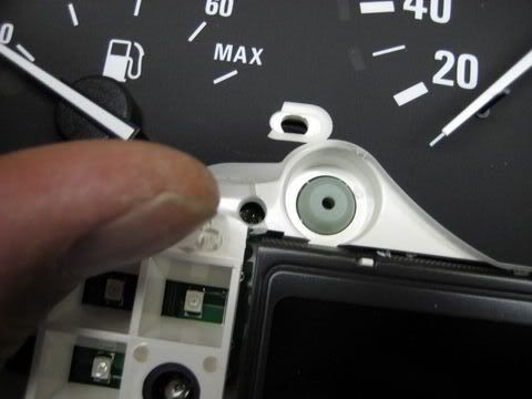
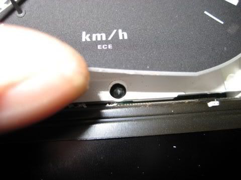
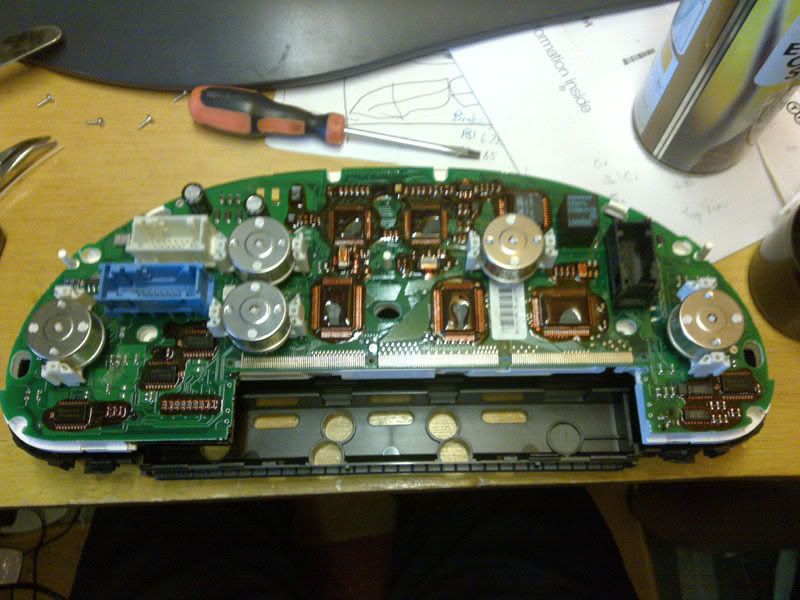
I removed and stripped the cluster down. I had to drill four 5mm sized holes to gain access to the four Torx (Tx 9) screws that hold the white plastic LCD carrier to the circuit board (and also clamp the ribbon, applying pressure to it).

This was quite a daunting task but it turns out that it's not so difficult (careful measuring/marking and bending back the dial backing - grey on mine). Also, from what I can see, there are no ill effects to the lighting on the cluster after doing so.

Drilling means that the dial needles do not need to be removed; from what I understand this is no bad thing as when the needles are pulled up, they tend to pull the spindle up from the motor and ruin the return spring in the process, another problem and cost - this is avoidable.

In the end I had the dials and the bare lcd hanging underneath. I took this back into the car to check where the connection was bad (circuit board or LCD). I found that the problem was at the circuit board end of the ribbon, but the pixel loss had got much worse.

I reckon that just moving the LCD section, thus flexing the plastic ribbon, had cracked the tracks in the ribbon. There was no doubt that just flexing things had made them much worse.

Some people say that increasing the pressure between the circuit board and the ribbon solves the problem. Moving things about to enable you to add packing (eg thin strip of card) might end up making it worse, so it's likely that the ribbon would have to be renewed - this was the case for me.

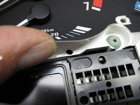
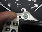
All traces of the oem adhesive had to cleaned off the board and LCD, some electrical contact cleaner and my nail did the trick. You can see the cleaned contacts in the following picture and I do apologise for the slightly blurred image.

Image


Aligning the ribbon with the LCD section was probably the most awkward step as you can't easily see the 'tracks' on the LCD glass (holding it an angle to the ight helped). Once that was sorted, the ribbon would also align with the circuit board contacts. The ribbon is held in place by the LCD clip - no adhesive required.

The ribbon was then folded up and sat quite neatly in the white lcd carrier, in the correct position to be fitted to the circuit board. I added a couple of strips of photo paper behing the rubber pressure pads, to increase the pressure by a bit, though I suspect this wasn't really necessary.
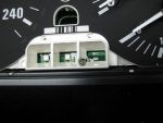
The LCD assembly was then re-fitted (using the four Tx9 screws) and the unit returned to the car for a test. It was a great relief to see everything working properly under 'Test 2' in the secret menu. See picture:

Image


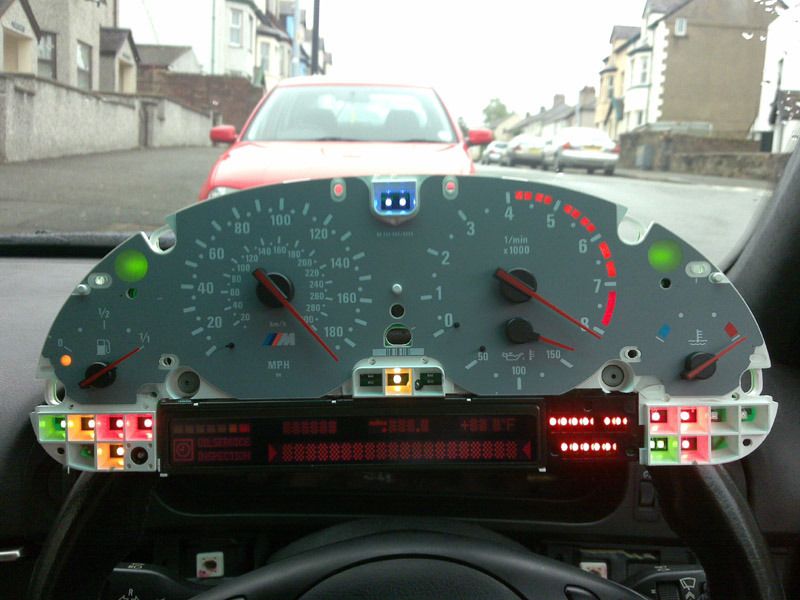
Everything was bolted and clipped back together and the instrument cluster finally re-fitted to the car.

If anyone has the pixel problem and don't want to send their instrument cluster away, then it is possible to renew the ribbon yourself cheaply. All you need is a lot of patience and some confidence.

As long as you don't break anything, if you fail to get the pixels to work, you still have the option of sending it away.

I hope this helps anyone who's considering undertaking the job themselves.
 
#3 ·
I didn't take that many pictures I'm afraid.

However, have a look at THIS LINK, it has several high quality pictures and it contains the locations of the holes (pics 10 to 13).

Incidentally, the guy in the above link states that the screws are Tx10, but on mine they certainly were Tx9. Also, he states that it's easier not to remove the screws. I found it much easier to re-fit the LCD carrier after removing the screws but make sure they don't get lost inside the cluster when you re-fit them - my Tx9 driver seemed to grip the screws well.

Screw heads are 4.4mm diameter, so a 5mm drill should give you a nice clearance to remove them with the driver.

When re-fitting the white LCD carrier, one leg (a pin that fits through the circuit board, powers the small bulbs) had to be bent a little bit. There's a motor for the oil temp gauge that's a bit in the way, a gentle bend to the pin helps to get everything back nicely (I'm not talking about a big bend here, only a few degrees that won't harm anything). You can just about make out the pins in the 14th and 15th pictures in the link.

HTH.
 
#4 ·
Yeah, show us where and how you drilled the holes?
 
#5 · (Edited)
1st hole:

Image


2nd hole:

Image


3rd hole:

Image


4th hole:

Image


Edit: These four pictures have been taken from the thread I've linked to in the above post. They are 'Edwin's' pictures (from bimmerboard.com) and I've linked them to his photobucket account. I just wanted everyone to know and for Edwin to receive his due acknowledgement. Thank you Edwin for such wonderful pictures.
I welcome anyone to use any of my photobucket pictures, as long as I'm acknowledged in a similar fashion.
As I've previously mentioned, I did not take many pictures. If I go back to this one day, maybe I'll take some shots myself. However, Edwin's pictures are very high quality are in focus and they do show what was required.


I lifted the instrument backing.
I carefully measured out and marked the locations for the holes.
I then drilled a small pilot hole (2.5mm iirc) to double check the locations.
I then used a 5mm drill bit to drill out the holes so the screws could come out.

I used a cordless drill with variable speed (ie not on/off) so I had better control over the drilling.

The instrument backing covers the holes so there's no chance of them being visible once everything is back in it's place.

HTH.
 
#8 ·
Thanks for trying this and then posting your results.
 
#9 ·
I'll be 100% honest. I found the DIY and a chinese ribbon cable and attempted this repair. It was absolute failure. Ended up sending the cluster to VDOrepair.com and got good service from them and cluster is perfect now. Not saying this is not a valuable thread or not to try it, just saying, its not a forgone conclusion that all will go well.
 
#11 ·
Thanks for the writeup. Very nice

One question....

Do you mean LED???? I don't see the LCD in here, or am I missing something
 
#12 ·
There are many stages at which things can go wrong causing it not to work afterwards. If you feel 'up to it' it might be worth a try, that's all I say. It's pretty cheap (ÂŁ26) and you don't have to go crawling to BMW for their goodwill etc (even if they do allow you a replacement, why should you even have to pay an hour's labour to fix 'their fault'... - this is a typical BMW response - don't get me going on that!).
Like I said, mine has no warranty and I didn't want to go asking BMW, it was either repair it myself or sned it away for about ÂŁ100 or failing that, buying a new unit (very unlikely at their prices).

If things go wrong then stop and send it away to be repaired professionally.

Remember, you don't need to touch the dial needles.


A few more tips.

When carrying out the repair you really have to be very careful and extremely patient:

Mark the hole locations very carefully and drill the holes gently, you don't want things to jolt as you push through. Pilot holes help and you can go up in small drill size increments if you want (ie every 1mm or so).

Prise the LCD carrier gently from the circuit board (after removing the four Tx9 screws). The three pins either side (carrying power to the small bulbs) are pretty stuck. Even pressure with a tiny rocking motion gets them going. I also used a butter spreading knife to help move things (very useful tool - thin, no teeth and surprisingly strong!). Make sure you don't affect the 'tracks' on the circuit board.

Be gentle with the LCD glass screen. This is pretty thin and the glass can easily be damaged. You need to release the metal frame's clips to remove the screen, use only enough pressure to release the tabs, don't go squashing the thing into oblivion or the glass will crack. Don't lose the small grey rubber bits either, they're from under the lower section of the LCD.

Ensure you remove all traces of the oem adhesive. Electrical contact cleaner and a nail are ideal - the cleaner won't harn the circuit and you have a good 'feel' with your nail. I suppose a plastic spatula would also work well if you don't want to get your hands covered in stinky, cold contact cleaner solution. After cleaning I ensure that the contacts were spotless by gently rubbing them with a fibre pen (I mean gently, very lightly and only a couple of strokes). Then another squirt of the contact cleaner to remove any fibre/debris.
I only used the contact cleaner and my nail on the LCD. I had visions of the allready almost invisible tracks dissappearing entirely if I used the fibre pen on them.

Take plenty of time to ensure the LCD glass tracks and the plastic ribbon tracks align up perfectly. If you don't then the other side (ie circuit side) will not align either. Also, I discovered that the glass needs to fit tightly to one corner of the white plastic carrier, if you've reached this stage you will know what I'm talking about. You really need to take care on this step. Have a break before tackling it, so you're fresh and in the right mood to get it 'spot on.' Make sure you get some peace and quiet too, nothing worse than being nagged just at that crucial moment!

Once the LCD side is in, you need to fold the plastic ribbon so the other contacts are just on top of the rubber pressure pads. It won't want to stay in position to start with, but keep on working it and the ribbon will take on a new 'S' shape and will stay there. You can then test fit it to the circuit board. Hopefully it will align up perfectly. If it doesn't, go back and adjust whatever needs to be adjusted, even if it means removing the LCD again; did I mention you need 'patience!' I had to re-fit the LCD metal frame four times because of this.

Once everything is aligned and in position, nip up the screws and press them six pins (3 either side) home gently. Don't go mad with the screws and 'give them a bit more' as the plastic will crack, there's not much 'meat' there.

Test the cluster once you're at this stage (secret menu Test 2), if it doesn't work then be prepared to take it appart again and sort it out. Something might have moved as you tightened the screws etc (that word 'patience' again!!). Mine worked without a hitch but I would not have been surprised at all if it wouldn't have.

Take another break as you're bound to make a silly mistake as you fit the plastic covers. Ensure that all plastic burrs (from the drilling) have been removed, they will find their way inside the screen and annoy you in the car, they easily become 'statically charged' and stick to the inside of the screen.
Fit the eight Tx10 screws that hold the back plastic to the instruments. Ensure the 'P R N D - 1 2 3 4 5' screen is 'in' and in it's proper position, it moves easily if you hold the instruments upside-down.

Don't drop the whole instrument cluster. It's pretty slippery! Carry it in a bag rather than in your hands. It would be awfull if you damaged it now!


Thanks for the writeup. Very nice

One question....

Do you mean LED???? I don't see the LCD in here, or am I missing something
It is an LCD screen. The five bulbs at the rear of the cluster provide white light (or 'close to' white light).
This light is filtered by a coloured plastic strip attached to the LCD carrier just behind the actual LCD (it's mainly orange, but a little yellow and green iirc), which gives us the nice colours. The LCD either allows light through or doesn't.

The control for our LCD opens up the correct path for the filtered light to pass through, giving us the shapes for the letters/numbers and graphics etc. I think it's all done with polarized filters/light and the liquid crystals either being in line, or not, with the filters. I'm sure wikipedia would have a nice explanation of how we use LCD's to give us shapes - but remember it's the backlit variety.

HTH.
 
#13 ·
Success in repairing my cluster!

So I have been reading up on how to do this project since I bought my car last June, and I finally got around to doing it. I ordered a new ribbon cable from LCD pixel failure repair for BMW instrument cluster, MID radio & OBC unit. and it took a few weeks to show up. The package was the ribbon cable, new foam for putting pressure on the cable, and good instructions(not as detailed as some might like but good enough to get-er-done).

I started by pulling out the speedo/cluster and taking it apart. If you decide to do this just know you will need patience, and a well lit work area. Taking apart the speedo was a little complex, but once I figured out the connectors were also holding the case in place, it popped right open. I decided to use a drill, and drill holes to undo the screws holding the LCD on vs. taking off the needles. I just eyeballed it so I had to drill extra large holes but this is not a problem since all the holes will be hidden. Once I took the LCD off I got to see the real problem.

The ribbon cable they use looks like it was put on with some type of glue, and the contacts were corroded. I used a credit card to clean the LCD, and some nail polish remover to clean the PCB side(this took about 15-20 mins of scrubbing). The new ribbon cable looked much beefier, and very well made. The new ribbon cable uses compression instead of glue to be held in place. I lined up the ribbon cable to the PCB, and taped it in place with scotch tape. I took the suppled foam that had a sticky side, and cut it into three pieces. I stuck the new foam to the back side of the ribbon cable(PCB side). I then put the LCD back in place, and lined up the ribbon cable. Everything gets snapped back together compressing the ribbon cable to the contacts. I had to test the cluster twice before I got everything lined up right. The first time I followed the instructions that told me to stack the new foam on the old foam but that didn't work, so I just stuck the foam right to the ribbon cable.

This is not meant to be a "How To", but more of a motivator and lessons learned type of post.

Things learned:
- Make sure you clean everything before putting it back together, and don't forget the inside of the clear plastic.
- Take your time when opening the case... Drilling... Cleaning... Just take your time! Total project time about 3 hours(YTMV).
- After you drill clean your area because there will be plastic bits everywhere.
- The screws that hold the LCD in do come all the way out!


If you have been waiting to do this, and you have patiences, then I would recommend going for it! I read a lot of posts warning not to attempt this, but it was't that hard. If you can take apart a laptop you can do this. If you need help or have questions feel free to email me at wfkvr6@gmail.com
 
#14 ·
Thanks for keeping the thread alive. I am now subscribed to it, as I just ordered a new ribbon for my car. I will post my results when done. It may be a few weeks though. I have confidence in my abilities, but also have an ace in the hole - that being a friend who's father repairs electronics, mostly older stuff, like original jukeboxes, radios, TV's, etc. So if I have a problem or just want the help I can access it locally.
 
#15 ·
Well I'm here to say another cluster has been successfully repaired! My ribbon came in the mail on Friday, so I immediately removed the cluster from the car. It took me an hour to get it to the point I was ready to remove the 4 screws that I just drilled to expose. I had to stop there because I didn't have a T9. This morning I went and bought one and finished the job. I had to take it back apart once for a little massaging. Total time was about 3 1/2 hours. This work deffinately isn't for the faint of heart! You need some electronics background or automotive background to be safe.

Thanks again to everyone who posted previously about this, it was a great help!
 
#18 · (Edited)
Help!

Ok I could use some help from the ones that have attempted this. I am partly though the tear down, I have remove the 6 screws from the front (Nothing Drilled yet) and for the life of me I can't get the back cover off. I have unclipped the two clips down neer the lcd and based on the instructions it appears the back should be able to come off. Am I misreading and I need to drill first or something?

Edit: Nevermind, Missed the part of breaking the tabs off each of the 3 connectors.
 

Attachments

#19 ·
I just fixed mine too!

Just DIY'd my dead pixels as well as wanted to chime in.

The key to 100% pixels is alignment of the new ribbon cable and the pressure the silicone inserts push it against the LCD. The whole thing is pretty daunting but patience and care is the key. You definitely want to be careful when the cluster is flipped over not to damage the speedo/fuel/tach/temp motors as they are very delicate. The trick to good pressure is to use thick photo paper (I doubled up the strips for each so now I have super bright LCD pixel display lol).

I bought a kit from ebay for $30 and saved myself at least $300 by doing it myself instead of sending to VDO for repair.

If you want to do it yourself--go to this guy on ebay: csiboreszkudo

BRAND NEW LCD RIBBON CABLE BMW E38 E39 X5, 5 7 SERIES - eBay (item 330537198963 end time Mar-26-11 01:19:06 PDT)

This guy has THE best video instructions...might be the only video instructions around...very very detailed and useful in noting tricks/caveats.

Be brave and learn to do this yourself!!! Very fulfilling feeling after fixing this. Good luck.
 
#20 ·
Pixels fixed - gauges a little off

Thanks to all the great posts on how to fix the pixel display - i took on the repair and successfully fixed the pixels. They look great, unfortunately i managed to get some of my gauges out of whack. I was being careful about not touching the needles however while blowing compressed air on display to remove some of the plastic drilling residue the needles got blown around a bit. Now my speedometer doesnt seem to notice a decrease in speed very quickly and my temperature gauge is reading low. Any suggestions on how to proceed calibrating or getting it fixed?

thanks for the help, love this board.
a
 
#21 ·
A bitof trial and error, twist them in the correct direction a tiny bit at a time until they are pretty close.

How much pressure did you use? They are pretty stiff on the spindles and are quite tough! I don't know about the speedo, maybe some use will help. Is it possible that the spindle was bent whilst you were handling it?

If all else fails, there are people who can replace tge various parts but you'll have to post it off.