BMW M5 Forum and M6 Forums banner
521 - 540 of 575 Posts
Thank you for the explanation. I get it. So if we go OEM Manual, the tray would have cigarette lighter and EDC. But you are creating a 2nd version of the tray with the EDC and POWER button and no cigarette lighter. I love that option, but i need the cigarette lighter for phone charger, etc. (Or maybe i reroute the lighter someplace else) Either way, appreciate you creating these, so awesome. Were you able to find an original part and scanned it?
we do have a 3D scanner but no I just measured it out and created my own. The original is a bit screwy because it expects there to be an under-tray id rather just delete.
 
we do have a 3D scanner but no I just measured it out and created my own. The original is a bit screwy because it expects there to be an under-tray id rather just delete.
Makes sense. So great! thank you very much, i am excited for your progress

we do have a 3D scanner but no I just measured it out and created my own. The original is a bit screwy because it expects there to be an under-tray id rather just delete.
I am new to the Forum. Is there a way to DM? Would love for you to stay in touch with your progress. Thank you so much. Brian
 
Makes sense. So great! thank you very much, i am excited for your progress


I am new to the Forum. Is there a way to DM? Would love for you to stay in touch with your progress. Thank you so much. Brian
I think it wont let us DM since we have too few posts. You can email sales at euromod.ca (replace at with @ lol).

I'm running a fairly finished version of the oddments tray in my car at the moment, but I realized a bit late in the process that the entire center console trim is retained at the front by these tiny little clips on the oddments tray and the bracket that sits below it... This is a terrible design on BMWs part, so I need to sort out an alternative. Currently I'm thinking to design a simple bracket that I can inlay strong magnets into and then add some magnets to the oddments tray. It would be a VERY strong but easily servicable setup.... but I'm just a bit frustrated with that so I moved onto the SMG paddle covers for now.
Image


Here's some pics of the preliminary modelling of that. Damned BMW made these profiles so bloody complicated...I'm thinking I may go old school and use modeling putty to mock it up on the wheel and then 3D scan that... ugh.

Image
 
Figured this maybe the appropriate audience before starting a new thread.

Issue: The DSC button/function does not work at all and I have the following code 5E5B DSC Button.

12/2006, 2007 model year. Build date with VO set to 03/2007
SZM has adjustable bolsters, heated seats, parking sensors and TPM button (!).
The car is still on jack stands, BRAKE and (!) are illuminated on the dash, in the idrive menu it showing TPM trying to reset.
CAS/LMA FA_WRITE'd with 2MA and +DOFF and All modules SG_CODIERAN'd with no errors.

Per E39 Source Move pin 41 blue wire for DSC passive to blue violet (TPMS) pin 6 in the driver side wheel well, leave blue violet not plugged in. Move blue wire from DSC OFF connector position 3 (blue wire) to position 6 on SZM, will have to remove blue/violet TPM wire and leave disconnected.

There is nothing in pin 6 at the ABS Connector X18303 at the on my car.
There is nothing in pin 3 at the SZM Connector position 3 on my car.

I did a little more reading and CHARIOT solved this already. All is resolved when moving pin 41 to pin 6 in the ABS module. I've seen conflicting information as to whether pin changes at the ABS module was necessary in this thread and I am confirming I needed to move 41 to 6.


Image

Image
 
E39 source switched wires around on both sides effectively doing nothing. Pre-LCI there is no need to swap any wires for ABS or SZM module. Once you code the them for the manual everything should work just fine.
 
Thank you all! Got to drive the car around today!

2 issues present that weren’t before the swap

1. The car keeps telling me to release the parking brake. Ista shows it is always in operation no matter handle up or down and therefore check pin 38 at the ABS module.

2. Post cat O2 CEL, ran the car open downpipe a few times hoping it goes away. Replaced the upstreams when I got the car maybe its just time to replace the post cat…
 
Ok so I'm afraid my situation is not as simple as swapping the O2s and pin 38 not seated on the ABS module. Hoping someone can chime in and help me understand what I did wrong here:

Per the wiring diagram, Pin 1 on the neutral sensor, Pin 2 on the RPM sensor and Pin 1 on the gearbox temp sensor all ground to X6459. E39 source says he ground these all together by splicing into one of the thick brown wires in the top left corner of the DME box.

If neutral sensor pin 1 is followed beyond the X6459 it goes into Pin 6 on the X60002 connector. So I assumed that was a DME grounding pin and crimped all the above mentioned wires together, and then spliced them into the wire that was in position 6. I think I made an incorrect assumption there.

Is the correct way to wire this to crimp together Pin 1 on the neutral sensor, Pin 2 on the RPM sensor and Pin 1 on the gearbox temp sensor, then run it to ground in the back left corner and then run a ground from there and splice it into Pin 6 on the X60002?
 

Attachments

RPM Sensor:
-There was no reason to touch pins 1 and 2. They could have stayed where they were and be fine.
-Pin 3 needs to go to Pin 22 on the DME X60002

Gearbox Temp Sensor:
-Pin 1 should correspond with Pin 10 on your X60681 (manual wiring harness) and connected to Pin 6 on X11 (SMG harness) which already terminates at X6459

Neutral Sensor:
-I ensured Pin 1 terminated at Pin 6 on the DME.

Also, I don't believe that X6459 is what you have circled on the photo. It is a butt connector within the DME box.
 
More progress overnight, I got the SMG transmission out. Exhaust, heat-shield and driveshaft came out pretty easily. I even mentioned to my friend how easy this was going along. You might know this as foreshadowing and probably know what is coming unknown to me! Got to the trans, removed wires, removed rear o2 sensors, etc. Began loosening all the e-torx bolts around the bell housing. Had to use my entire set of locking extensions from HF Tools, made life so much easier not having the extensions fall/pop out. Having a nice time I say...... View attachment 876782 However, this project really had a close call. One of the starter e-torx bolts had been overtorqued and rounded from the previous clutch job prior to my ownership. Needless to say that was an absolute PITA and came close to possibly dropping the motor and trans together in order to get to this. I used my 8mm bolt extractors to hammer on with my extension train and managed to get it off somehow....luck was on my side. MAKE SURE TO USE THE PROPER E-TORX SOCKETS! IT IS NOT FUN REMOVING THE TOP ONES, especially if they are rounded/over-torqued. Go slow and make sure you are fully seated when getting these off. View attachment 876784 Got the old SMG out, surprisingly the wiring didn't look too bad near the PLCD sensor. I HIGHLY recommend a low profile trans jack or having someone with a lift and a trans jack. I did this with a regular jack, that was much more difficult to balance the trans coming down. This thing is heavy and will want to rollover coming down if you are not balancing this as it comes down if you do it this way! For some reason, my pilot bearing popped out with the trans. Not sure what that was about. Haven't pulled the clutch and flywheel out yet but they looked well beat for a unit that has done 50+ launch control starts. It's also a great time to replace all O2 sensors, I will be doing all four since my car has had lambda errors. View attachment 876786 View attachment 876788 
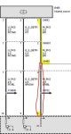
I ran the last hydraulic line from the clutch master to the clutch slave. Being that the trans was out, it made it a lot easier to fish the line up from inside the car. The line runs from the master, over the trans tunnel and into a grommet. Look at my photo if you need a reference. Don't forget to check the rubber o-ring and locking clip on both ends. View attachment 876790 The interior no longer looks like a absolute mess anymore and is all fully back together and functioning. The EDC and MDM buttons are functioning the way they are supposed to and I tested all the buttons to make sure they work as intended. Off to Hawaii I go for a week and back at this immediately when I get back! View attachment 876792
what did you do with yaw sensor that der the seat , how did you connect it and made DSC works properly because i did some wiring there and my dsc is always off now i don't really how to fix it now so i will be thankful if you give me more info about it.
 
what did you do with yaw sensor that der the seat , how did you connect it and made DSC works properly because i did some wiring there and my dsc is always off now i don't really how to fix it now so i will be thankful if you give me more info about it.
calibrate the longitudinal sensor with INPA. See my spreadsheet above for info on how to do so (it's in the DME module). Doesn't seem to be an option in ISTA or with most scan tools (like an Autel)
 
Just wanted to post an update on the 3D printed oddments trays. I've put the pre-LCI one on pause for now as I'm working on swapping an LCI car for a customer. The LCI version is easier in some ways, and more difficult in others (curved top) but regardless I'm getting close to that being complete. Have the mounting screws, knotches, and cut out all mapped out perfectly to the center console trim based on a 3D scan of the non manual tray, and by using photos online to get proportions for the button and tray. Printing out what is hopefully my second to last mockup tonight which will just have the tray, and then tomorrow I'll print out the version with the button to try in the car.

Once the design is at a point I'm satisfied with I will put these up for sale as well :)

Image
Image
 
Shoutout to @jakkuh - that's my car in the photos above.

I bought the car with a toasted SMG clutch/flywheel and sourced an M3 GS6-53BZ along with matching clutch/flywheel. I took the car to Jakkuh's shop and he took care of the rest - the boatload of additional parts, having the driveshaft extended, all the finicky and frustrating wiring, coding, and developing a 1:1 resin printed oddments tray. He did like 15 revisions or something on the tray to make it perfect. It looks 100% factory and feels fantastic. Everything works as it should, PDC, reverse lights, HUD, and I can still turn traction control off.

I considered a couple different shops and ultimately chose him, primarily due to his expertise with the wiring and the oddments tray. He is a perfectionist with deep S85 knowledge and I am super happy with how the car turned out, would recommend folks in the PNW considering S85/S65 work get in touch with him. I'll be back for more S85 goodies in the future.

Also after driving just 120 miles, and reading about all the folks who say the SMG is better suited to this car, I absolutely couldn't disagree more. The 6MT blows the SMG out of the water IMHO. :alien:

Image


Image


Image
 
521 - 540 of 575 Posts