This post is a work in progress, and over the next few days I plan to verify a few more things.
So, you like the look of the newer LED tail lights but you've been told they don't work without the official retrofit kit with ballasts. Well, whoever told you that was very possibly WRONG!! If your car has a LCM II (e39s before MY99 that didn't replace the LCM), you would benefit from the retrofit kit as it's about the same price as a new LCM (LCM IV). However, if you have an E39 with an LCM III or newer, you can simply code your LCM to be the ballast that everyone charges a crap-ton for.
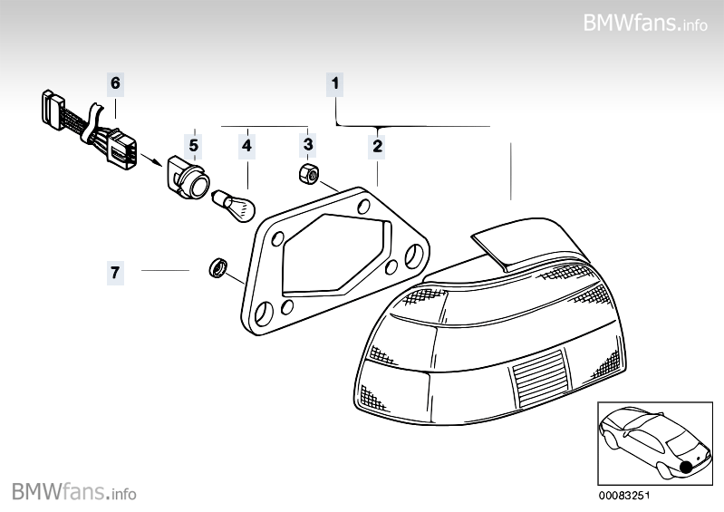
This swap requires:
- drilling new mounting holes in the car's light buckets
- hammering a little bit for clearance of the new light (different shape)
- inserting pre-crimped wire leads into a plug
- soldering some wires (please don't cheap out and use some universal crimp connector)
- Light Control Module coding via GT1, SSS/Progman, NCS expert,BMW Scanner v.1.40, or Autologic (there may be others)
NOTE: if you don't have the coding tools the regional sub-forums are tools of great value, and you can often find the computer coding tools you need.
Chassis Bashing:
The blue line is where you'll need to bash (2 minutes with a hammer for me) and drill *note*, I forgot the arrow pointing to the other lower mounting hole I drilled):
![Image]()
![Image]()
Fit comparison (after bashing) - OEM US facelift Celis lights:
![Image]()
vs. pre-facelift OEM hellas:
![Image]()
Electrons in motion (bench testing):
Not really sure why everyone asks the proper voltage for these lights, it's only printed on them.....(NOTE: LEDs are current driven devices, and to get the driving current we use P=V*i, or 1.2W/12V = ~108mA):
![Image]()
Unfortunately, all my power supply could muster was about 10.2V which was just enough to illuminate the LED tails, albeit under driven as seen below on the multimeter (only ~33 mA).
![Image]()
Take some adderall or something so you don't mix this up:
More wire prep, this time on the Celis plug (IIRC, this is also the right):
![Image]()
Planning to solder my Celis wires for the right side, and comparing WDS wire colors to actual - WDS was right, I just wanted to be careful:
![Image]()
Feeling cramped:
In-car workstation (400W inverter hooked directly to the battery to power the 40W soldering station):
![Image]()
Left tail light just before shrink wrapping the solder joints and re-looming the remaining wire:
![Image]()
Final testing - if you're wondering about the varied tail light intensity, the tail lights are just sort of propped up at different angles, i assure you they're the same (the pre-facelift lights are not actually on, that is just the camera's flash bouncing off the tail light lens)
![Image]()
![Image]()
They are installed now, my LCM IV is coded and everything is A-OK.
I did confirm that the LCM acts as the ballast via voltage measurements (I plan on corroborating that by measuring current, too...when it's not dark outside), 11.8-12.2V @ idle while the battery was at 14.2V.
I'll post up wiring later, it's rather simple, you do need to cap one of the original tail light wires as it's not needed.
So, you like the look of the newer LED tail lights but you've been told they don't work without the official retrofit kit with ballasts. Well, whoever told you that was very possibly WRONG!! If your car has a LCM II (e39s before MY99 that didn't replace the LCM), you would benefit from the retrofit kit as it's about the same price as a new LCM (LCM IV). However, if you have an E39 with an LCM III or newer, you can simply code your LCM to be the ballast that everyone charges a crap-ton for.
This swap requires:
- drilling new mounting holes in the car's light buckets
- hammering a little bit for clearance of the new light (different shape)
- inserting pre-crimped wire leads into a plug
- soldering some wires (please don't cheap out and use some universal crimp connector)
- Light Control Module coding via GT1, SSS/Progman, NCS expert,BMW Scanner v.1.40, or Autologic (there may be others)
NOTE: if you don't have the coding tools the regional sub-forums are tools of great value, and you can often find the computer coding tools you need.
Chassis Bashing:
The blue line is where you'll need to bash (2 minutes with a hammer for me) and drill *note*, I forgot the arrow pointing to the other lower mounting hole I drilled):


Fit comparison (after bashing) - OEM US facelift Celis lights:

vs. pre-facelift OEM hellas:

Electrons in motion (bench testing):
Not really sure why everyone asks the proper voltage for these lights, it's only printed on them.....(NOTE: LEDs are current driven devices, and to get the driving current we use P=V*i, or 1.2W/12V = ~108mA):

Unfortunately, all my power supply could muster was about 10.2V which was just enough to illuminate the LED tails, albeit under driven as seen below on the multimeter (only ~33 mA).

Take some adderall or something so you don't mix this up:
More wire prep, this time on the Celis plug (IIRC, this is also the right):

Planning to solder my Celis wires for the right side, and comparing WDS wire colors to actual - WDS was right, I just wanted to be careful:

Feeling cramped:
In-car workstation (400W inverter hooked directly to the battery to power the 40W soldering station):

Left tail light just before shrink wrapping the solder joints and re-looming the remaining wire:

Final testing - if you're wondering about the varied tail light intensity, the tail lights are just sort of propped up at different angles, i assure you they're the same (the pre-facelift lights are not actually on, that is just the camera's flash bouncing off the tail light lens)


They are installed now, my LCM IV is coded and everything is A-OK.
I did confirm that the LCM acts as the ballast via voltage measurements (I plan on corroborating that by measuring current, too...when it's not dark outside), 11.8-12.2V @ idle while the battery was at 14.2V.
I'll post up wiring later, it's rather simple, you do need to cap one of the original tail light wires as it's not needed.

")