

After doing this a few times to fully learn it, figured it may be useful to share the process with some tips and issues. This guide includes most basic information, but should be used to supplement the TIS document with some tips, and additional details that may not be clear or even mentioned in the TIS version.
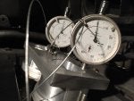
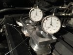
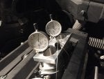
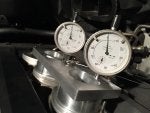
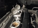
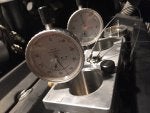
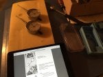
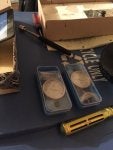
To start out, the BMW throttle synchronization fixture is helpful, but you may also be able to do this with two standard magnetic dial gauge fixtures. If you do this, you want to make sure everything is secure and as square as possible or you'll likely be wasting your time. Given the tolerances, you'd be lucky to achieve success with Harbor Freight dial gauges or similar.
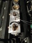
As reason for bothering, the cylinder 6 throttle on my m5 had began to strip the brass throttle actuation arm securing nut potentially from the 12 years of the motor torquing on it. Allowing the arm to twist just slightly introducing inconsistency into the system…
The Process Goals
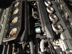
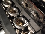
Each throttle is individually zeroed from the factory (those black plastic nut covers). By synchronizing you are simply allowing all the throttles to achieve their individual zero with the interference caused by being attached to each other. On each bank, the pull rod throttle is essentially the master, that the others need to be set downstream from. This is why you do it in the specific order.
The Pre-Process
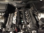
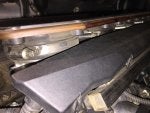
1. Remove cabin air filter channels to gain access to remove plenum.
2. Remove MAF to plenum tubes & oil separator tubes.
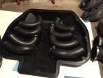
3. Remove upper plenum cover.
4. Remove throttle snorkels.
5. Unbolt lower plenum.
6. Loosen lower plenum oil hose clamps, disconnecting the front two (4X hoses from the front).
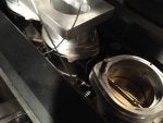
7. Remove the plenum, shaking loose the lower oil separator hoses.
8. Remove both throttle to plenum rubber gasket/mounts. If you are just trying to balance the banks to each other with the pull rods, you only need to remove the one on the side with adjustable pull rod. The cable ducts can remain in place.
9. Disconnect both pull rods from the throttle actuator motor side.
Syncing Process For the Banks
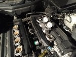
Now that everything is out of the way, time to start syncing the throttles.
1. Pull Bank 1 throttles up and screw in the adjustment screw between throttle 1 & 2 and 2 & 3.
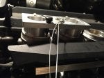
2. Put the shims in between the space between the end stop to prevent the spring from expanding back into the gap. This will give you a couple mm of free movement on throttle 1 with respect to 2 and throttles 1 and 2 with respect to 3 and 4.
3. Now place the fixture and dial gauges on top of throttle 1 & 2 (or similar). You now want to open and close throttle 1 a few times, setting the dial gauge to zero at the throttles closed/stop point. Do the same with throttle 2. Since throttle 1 is dependent on 2, moving 2 farther can interfere with 1. Both should still come back to zero if your fixture and gauges are secure.
4. Now that you have found the individual zero for 1 & 2 it’s time to free the shim between 1 & 2. You do this by screwing the adjustment screw in.
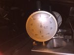
5. At this point, unless you got extremely lucky one or both of throttle 1 & 2 will be off of zero on the gauge. Work the adjustment screw until both are zeroed again. You can be up to 0.01 mm away from the zero (two ticks on the large ring of the BMW gauges) and still be within spec, but it’s possible to get them right on.
6. Once zeroed, test them a few times by opening 1 & 2 gently by hand, making sure they go back to the zero. This is where I found one major bit of trouble. As it turns out, the movement of the throttles can very minutely unscrew the tip of your dial gauge, making your readings walk away from the zero. This is especially common later in the process. If you see this, pull the gauges and tighten them up, potentially even with some pliers to get it secure. Probably a good idea to restart the process if this happens.
7. With the shim still between 2 & 3, move the free shim to 3 & 4 using the adjustment screw.
8. Place the dial gauges on 3 & 4, and perform the same process to individually zero 3 & 4 while disconnected from each other and 1 & 2.
9. Remove the shim and complete the zero process between 3 & 4.
10. Now with groups 1 & 2 and 3 & 4 zeroed, it’s time to zero the two groups to each other. With the shim between 2 & 3 still in place, place the dial gauges and individually zero both 2 & 3 (1 & 4 will remain zeroed with respect to their neighbor, 2 & 3 respectively).
11. Once the dial gauges are zeroed, remove the shim, and use the adjustment screw to bring 2 & 3 back to zero on the gauges.
12. At this point, Bank 1 is completely zeroed. You now preform the same process on bank 2, just in a different order, since throttle 8 is equivalent to throttle 1 (opposite direction). Begin with 7 & 8, then 5 & 6, then 6 & 7 to bring the two groups and bank together.
Syncing the Banks to Each Other
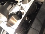
1. Remove the adjustable pull rod entirely. Be very careful with this, as it is possible to destroy the throttle arm by putting too much pressure on the arm with the ball (held by the little gold nut with the locking wings wrapped around it).
2. Get the pull rod as close to 133mm from center to center of the ball caps (you can be up to +0.8 mm off, but might as well get it right).
3. Pop the arm back on to throttle 6, but keep it disconnected from the throttle actuator.
4. Using both fixtures, put the dial gauges on throttles 3 & 6.
5. Using the rod to open the throttle banks gently, individually zero both throttles 3 & 6 with the dial gauges.
6. Now attach the rods back onto the throttle actuator. You will likely see the dial gauges move a bit, but in my case they returned to zero at the motors resting point. Note, that the motor may have enough preload to push the throttles slightly past zero.
7. Adjust the pull rod as necessary to bring both back to zero. Note here, the throttles should be very close to zero with the adjustable rod set at 133mm. The shorter or longer you make the adjustable rod, the more you affect the speed at which one bank opens with respect to the other. This is why the next procedure with DIS gives you a spec for 1% throttle.
DIS Actuation Test
Since I don’t have a working DIS, I omitted this step given that it actually isn’t an adjustment step. It’s just a step that verifies the bank syncing went properly, and throttle movement hasn’t been negatively affected by adjustment. Doing this process many times, I found that the closer to 133mm the adjustable rod is (which actually was nearly exactly where my banks zeroed to each other on the motor), the more likely you are to be within specification for bank opening rates. If you have to adjust the adjustable pull many quarter turns, then this step may become more of a necessity to make sure you are still within the rate spec. You can also mimic this test by holding the motor open slightly by hand, and making sure each bank opens at the same rate from zero using the dial gauges on throttles 3 & 6.
The Caliper 100% Test
TIS is pretty murky on this task, but again this can be achieved without DIS running 100% to the motor. Basically all this step asks, is that the adjustable stop screw on the motor spindle plate corresponds with 24.2 mm +-0.5mm measured from the throttle butterfly to the maximum point of the upper (wider) throttle wall using Bank 2 only (Bank 1, is not used in this task, and may have a different spec). Just have someone hold the motor spindle against the stop while you measure this. Do not adjust anything other than the motor spindle stop hex screw in this task. This 24.2mm may not be perfectly consistent for each of throttle 5 through 8 because of their individual zeroes.
Hopefully this explains a bit about what to avoid when trying to interpret the TIS throttle sync process. Lot’s of these details are not clear in the doc, and took quite some time to figure out. It’s already long enough so feel free to ask questions for more detail.
To start out, the BMW throttle synchronization fixture is helpful, but you may also be able to do this with two standard magnetic dial gauge fixtures. If you do this, you want to make sure everything is secure and as square as possible or you'll likely be wasting your time. Given the tolerances, you'd be lucky to achieve success with Harbor Freight dial gauges or similar.
As reason for bothering, the cylinder 6 throttle on my m5 had began to strip the brass throttle actuation arm securing nut potentially from the 12 years of the motor torquing on it. Allowing the arm to twist just slightly introducing inconsistency into the system…
The Process Goals
Each throttle is individually zeroed from the factory (those black plastic nut covers). By synchronizing you are simply allowing all the throttles to achieve their individual zero with the interference caused by being attached to each other. On each bank, the pull rod throttle is essentially the master, that the others need to be set downstream from. This is why you do it in the specific order.
The Pre-Process
1. Remove cabin air filter channels to gain access to remove plenum.
2. Remove MAF to plenum tubes & oil separator tubes.
3. Remove upper plenum cover.
4. Remove throttle snorkels.
5. Unbolt lower plenum.
6. Loosen lower plenum oil hose clamps, disconnecting the front two (4X hoses from the front).
7. Remove the plenum, shaking loose the lower oil separator hoses.
8. Remove both throttle to plenum rubber gasket/mounts. If you are just trying to balance the banks to each other with the pull rods, you only need to remove the one on the side with adjustable pull rod. The cable ducts can remain in place.
9. Disconnect both pull rods from the throttle actuator motor side.
Syncing Process For the Banks
Now that everything is out of the way, time to start syncing the throttles.
1. Pull Bank 1 throttles up and screw in the adjustment screw between throttle 1 & 2 and 2 & 3.
2. Put the shims in between the space between the end stop to prevent the spring from expanding back into the gap. This will give you a couple mm of free movement on throttle 1 with respect to 2 and throttles 1 and 2 with respect to 3 and 4.
3. Now place the fixture and dial gauges on top of throttle 1 & 2 (or similar). You now want to open and close throttle 1 a few times, setting the dial gauge to zero at the throttles closed/stop point. Do the same with throttle 2. Since throttle 1 is dependent on 2, moving 2 farther can interfere with 1. Both should still come back to zero if your fixture and gauges are secure.
4. Now that you have found the individual zero for 1 & 2 it’s time to free the shim between 1 & 2. You do this by screwing the adjustment screw in.
5. At this point, unless you got extremely lucky one or both of throttle 1 & 2 will be off of zero on the gauge. Work the adjustment screw until both are zeroed again. You can be up to 0.01 mm away from the zero (two ticks on the large ring of the BMW gauges) and still be within spec, but it’s possible to get them right on.
6. Once zeroed, test them a few times by opening 1 & 2 gently by hand, making sure they go back to the zero. This is where I found one major bit of trouble. As it turns out, the movement of the throttles can very minutely unscrew the tip of your dial gauge, making your readings walk away from the zero. This is especially common later in the process. If you see this, pull the gauges and tighten them up, potentially even with some pliers to get it secure. Probably a good idea to restart the process if this happens.
7. With the shim still between 2 & 3, move the free shim to 3 & 4 using the adjustment screw.
8. Place the dial gauges on 3 & 4, and perform the same process to individually zero 3 & 4 while disconnected from each other and 1 & 2.
9. Remove the shim and complete the zero process between 3 & 4.
10. Now with groups 1 & 2 and 3 & 4 zeroed, it’s time to zero the two groups to each other. With the shim between 2 & 3 still in place, place the dial gauges and individually zero both 2 & 3 (1 & 4 will remain zeroed with respect to their neighbor, 2 & 3 respectively).
11. Once the dial gauges are zeroed, remove the shim, and use the adjustment screw to bring 2 & 3 back to zero on the gauges.
12. At this point, Bank 1 is completely zeroed. You now preform the same process on bank 2, just in a different order, since throttle 8 is equivalent to throttle 1 (opposite direction). Begin with 7 & 8, then 5 & 6, then 6 & 7 to bring the two groups and bank together.
Syncing the Banks to Each Other
1. Remove the adjustable pull rod entirely. Be very careful with this, as it is possible to destroy the throttle arm by putting too much pressure on the arm with the ball (held by the little gold nut with the locking wings wrapped around it).
2. Get the pull rod as close to 133mm from center to center of the ball caps (you can be up to +0.8 mm off, but might as well get it right).
3. Pop the arm back on to throttle 6, but keep it disconnected from the throttle actuator.
4. Using both fixtures, put the dial gauges on throttles 3 & 6.
5. Using the rod to open the throttle banks gently, individually zero both throttles 3 & 6 with the dial gauges.
6. Now attach the rods back onto the throttle actuator. You will likely see the dial gauges move a bit, but in my case they returned to zero at the motors resting point. Note, that the motor may have enough preload to push the throttles slightly past zero.
7. Adjust the pull rod as necessary to bring both back to zero. Note here, the throttles should be very close to zero with the adjustable rod set at 133mm. The shorter or longer you make the adjustable rod, the more you affect the speed at which one bank opens with respect to the other. This is why the next procedure with DIS gives you a spec for 1% throttle.
DIS Actuation Test
Since I don’t have a working DIS, I omitted this step given that it actually isn’t an adjustment step. It’s just a step that verifies the bank syncing went properly, and throttle movement hasn’t been negatively affected by adjustment. Doing this process many times, I found that the closer to 133mm the adjustable rod is (which actually was nearly exactly where my banks zeroed to each other on the motor), the more likely you are to be within specification for bank opening rates. If you have to adjust the adjustable pull many quarter turns, then this step may become more of a necessity to make sure you are still within the rate spec. You can also mimic this test by holding the motor open slightly by hand, and making sure each bank opens at the same rate from zero using the dial gauges on throttles 3 & 6.
The Caliper 100% Test
TIS is pretty murky on this task, but again this can be achieved without DIS running 100% to the motor. Basically all this step asks, is that the adjustable stop screw on the motor spindle plate corresponds with 24.2 mm +-0.5mm measured from the throttle butterfly to the maximum point of the upper (wider) throttle wall using Bank 2 only (Bank 1, is not used in this task, and may have a different spec). Just have someone hold the motor spindle against the stop while you measure this. Do not adjust anything other than the motor spindle stop hex screw in this task. This 24.2mm may not be perfectly consistent for each of throttle 5 through 8 because of their individual zeroes.
Hopefully this explains a bit about what to avoid when trying to interpret the TIS throttle sync process. Lot’s of these details are not clear in the doc, and took quite some time to figure out. It’s already long enough so feel free to ask questions for more detail.


")


