BMW M5 Forum and M6 Forums banner

"No communication possible with: Dynamic Stability Control" - but first, some verbiage

37K views 62 replies 5 participants last post by  dr_dirtg  
#1 ·
Hi -

Working through an issue here - not after a quick answer but instead, using it as a learning experience in wiring diagrams etc.

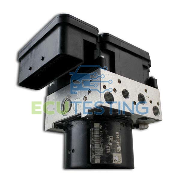
ISTA+ just says $topic. Is there a way to differentiate between the control unit (that's the comptuer, right?) and the actuator itself (the actual hydraulic unit, right?)

I'll check the supply power to the DSC computer module against its supplied grounds once I figure out where it is (but I can read the harness pinout). Fuses according to the wiring diagram (assuming 50A fuse 1 is for pump, 25A fuse 25 is for control unit?).

Looking ahead, I want to be able to craft a plan for testing the hydraulic unit, too.

I've attached some screenshots, hopefully they can better articulate what I'm attempting to.

---
[0] Supply, control unit, dynamic stability control (DSC)


944012


944013


944014


944015
 
#2 ·
#3 ·
Oh. So with regard to my original question, the hydraulic unit and the control unit are one piece. I was thinking the control unit was a super secret delicat electronic component that sat with everything else against the firewall or in the glove box.

I'll pull the covers and start testing pins!
 
#5 ·
The control unit is getting good power as it should. I've been reading up on CAN devices (in this case PT-CAN since that's the only bus that DSC is connected to) barfing all over the bus causing communication problems. I pulled the ALBFA and SZL fuses hoping I'd get lucky and single one of them out, but this time it fails differently - but still shows DSC red.I'm not sure how EDC still shows red since the drivers' front EDC cable isn't connected. Maybe it just needs data (e.g. starting, moving) before it faults.

Pretty sure I can scope the PT-CAN bus (I'm moderately proficient in this Rigol scope) but I'd rather not because, reasons. If it comes down to it fine, but I suspect something more sinister.

Looking for other ideas to find a definitive answer as to why DSC has failures. Found another few related posts but in lieu of spending $5k to swap parts, I've got the time and the equipment (probably) to give it a shot.

CAN BUS errors on BMW E60, advise needed - Pico Technology (nerds, my people!)
CAN bus problem very strange pls help (sometimes ebox fan fails? the car has been on jack stands for 5 months, no heat)
https://www.newtis.info/tisv2/a/en/e60-m5-lim/repair-manuals/34-brakes/1r9ALrM (DSC8 deep-dive)
 
#6 ·
I had to have my DSC module repaired after it went a bit crazy, sometimes it would work, sometimes it would have a tantrum and would show DSC failure soon after starting. Turned out it's just one of those things that happens. Had it fixed by these guys, worked great ever since:
 
#8 ·
I've had transient issues and failures of random systems in the past but concluded it was the voltage regulator. DSC was always one of the first things to error out. My battery was on a tender but still read 12.4v. I wasn't able to find an exact spec for battery level in TIS but I'd consider that low. It's been on a 2A charger overnight. The charger says 13.6 volts now but only 60% full. In times past with other vehicles I've seen this to indicate that the battery was not holding a charge, could not become fully charged. This part is anecdotal but I've seen people talk about how the car will disable other systems in an effort to preserve whatever battery power is left. If the right systems in the right order are powered down, then DSC can't make sense of what's going on or its power supply or signals are also compromised, a red herring.

I'll give this charge a few more hours, swap it bbn out with another AGM battery I've got on the shelf (not for starting, but for electrical system testing), get this old battery load tested, and go from there.

I just wish ISTA was smart enough to tell me enough information about power consumption and the resulting systems that were disabled because if that (if this in fact what happens?).
 
#9 ·
It had a voltage regulator 5 years ago, since then no problems at all. It was last year at some point the DSC started playing up, it just made the gong noise and threw an error. It was intermittent for a while, sometimes it would be happy and work, other times it would get upset. It did happen after a throttle actuator broke, but it's getting to that age where stuff just breaks and it's not often a coincidence.
I did recently flatten the battery by accident when diagnosing a locking issue and diversity antenna - too long on ISTA and not running the engine. After a charge the engine started and everything is back to normal, DSC didn't complain about that the way it did when it was playing up.
 
#10 ·
Funny, I too have murdered a battery before by keeping the cable plugged in for too long haha.

The module does the classic "wheeeeeeeeeen' noise when relay 15 engages. Of course this doesn't tell me much, it's probably got an independent component with a pressure sensor in the system that activates the pump to meet a minimum pressure level regardless of communication or connection with PT-CAN. But, at least this is a good sign that it's somewhat alive. No "gong" sound like what you described, though.

It's not a huge deal, using this as a functional exercise in using ISTA to troubleshoot a device, more experience with wiring diagrams, testing things by hand etc. In a weird way it's satisfying because everything on this car is computer controlled - it's nice to get down and dirty with testing lights and multimeters (but I could do without the suggestion of firing up the scope to diagnose PT-CAN :) )
 
#11 ·
Dan - where did you get your ISTA ? (and as a side note, does this site keep taking you to a need to update screen, totally not related to this site)
 
#16 ·
"Information on the measurement with 60 ohm: Disconnect an easily accessible control unit from the bus. Then measure the resistance on the connector between the CAN Low and CAN High lines."

That's an easy test. I reckon there's something going on with the PT-CAN, a bad actor maybe. All the codes pulled are from things attached to the PT-CAN. That's why I was pulling fuses last night.
 
#17 ·
ya - its an easy place to start. just need to see if those resistors are suppossed to be present by looking at wiring diagram or maybe searching a bit to see if someone already blazed this trail
 
#18 ·
Ahh it's not a big deal, experience reading the wiring diagram. I got this.

But....

"In order to prevent signal reflection, 2 CAN bus users (at the extremities of the powertrain CAN network) with 120 ohm each are terminated".

I don't know if that describes a process (e.g. i terminate them) or a statement of fact. I ask because there are more than the two CAN actors in the system than the "two" this document describes.
 
#19 ·
I didn't read it that close, but by it saying read your schematic to see if present, then I think it is a design feature, and will be present on some cars. you couild do it in reverse and just stick an ohm meter in there and see what you get, if you read 60, then its probably there!
 
#22 ·
I was reading up about how - among other systems - DSC is powered by relay 30G. Seeing as some of these other units are also reporting less than nominal states in ISTA, I threw a temperature sensor on it just to see what's up. When the car was woke, it read 99F. Now, 20 minutes after the door was closed, it's reading 145F. Just a few moments ago, I looked and it's less than 130F. I don't know what the normal temperature is but I don't like that. I'll give it some more time because according to TIS, 30G should switch off after 30 minutes[0]. New relay in the shopping cart, just in case.

I haven't tested to figure out what the culprit is but I also saw an energy diagnostic warning of something parasitic consuming in the range of 80-200mA. If the relay is malfunctioning this certainly could be where the draw is coming from, though I don't want to break out the books to figure out how much heat 80-200mA@12V generates.

---
[0] https://www.newtis.info/tisv2/a/en/...2/a/en/e60-525i-lim/repair-manuals/61-general-vehicle-electrical-system/1u18ALZ
 
#23 ·
Relay temp went back down to ambient when the car went to sleep. I still think 145F is quite warm for any component which doesn't have a (significant) load on it.

Tomorrow I'll put an ammeter between the battery negative and the negative cable to see how bad the draw is in sleep (if in fact there is one) and from there start pulling fuses to see what might be draining or shorting.

Regarding SLZ, the lense etc was replaced less than 10k miles ago. Im not saying new parts don't fail, but that would be unlikely - this still warrants a test at some point. The circuit board had no visible damage, it was just dirty. I was meticulous with my work and even had a second set of eyes double checking. At the time, the warning went away after replacing and recalibrating. Interestingly this time around, the error doesn't indicate failure but instead an inability to talk with SLZ. This bolsters my suspicion that the failure of these components is rooted in a single cause: a power supply issue.
 
#25 ·
Hey Dan - There is a functional test for the ABS system that turns the pumps on. You might try running that test for kicks and grins. See if it can activate it.
 
#26 ·
OH! Great find. Thank you.

So, turns out there are two resistors total on PT-CAN after all :)

I do a lot of tinkering, hobby electronics. Ots not uncommon to use a "pull-down" resistor to signify a true 0V, or the opposite of +VDC, for units on a shared BUS. This is common with units that need a 0 resting state or a 0 as part of their encoding. Lots of other BUS protocols use this like SPI, 1Wire (i2c), and to an extent RS485 (kinda). If one of these resistors goes bad theres no way for the unit to properly signal and communicate, which amounts to garbage talk on the BUS.
 
#28 ·
OH! Great find. Thank you.

So, turns out there are two resistors total on PT-CAN after all :)

I do a lot of tinkering, hobby electronics. Ots not uncommon to use a "pull-down" resistor to signify a true 0V, or the opposite of +VDC, for units on a shared BUS. This is common with units that need a 0 resting state or a 0 as part of their encoding. Lots of other BUS protocols use this like SPI, 1Wire (i2c), and to an extent RS485 (kinda). If one of these resistors goes bad theres no way for the unit to properly signal and communicate, which amounts to garbage talk on the BUS.
[/QUOTE
likewise, if you have an undervoltage situation, it will be garbage talk on the bus
 
#31 ·
Got my own automobile problems right now, but I did a quick scan on CAN bus - it looks like there are 2 different voltages that it can operate at. Did you figure out which our cars work at? Do you have an oscilloscope? Between measuring the resistance and checking voltages, the next thing you need to check is if you have a clean signal.