

Firstly before we get into the DIY I’d like to say a massive thank you to a few members. Without the help of certain people on this board there would be a whole lot of work that wouldn’t be completed or even attempted by a lot of members.
Its these people that help to make this board what it is, and give power to owners to get to know their Beast a little more, whilst saving some cash, improving their car, and getting some self satisfaction from accomplishing what perhaps they never thought they could do.
Raikku, for all of his DIY’s of which some relate to this job, for his support to other members and willingness to help whenever, wherever possible/
68FB, who has tackled this job also and explained a few things along the way.
M5Daemon, who gave me a gentle nudge in the right direction when I had a couple of headscratching moments.
And anyone else who gave me the time of day to help me get this job done.
I’d also like to say quickly that this isn’t a thread designed to steal anyone’s thunder, we all know who the pioneers of jobs like this are on the board. Rather there are members like those above who are extremely busy, and can’t write down and document every single job they do for the good of the community. Hopefully, this is where I can come in to try and do my part at giving something back
Right, so the thanks are over, we’ll start at the beginning. I have a MY2000 built in February 2000, meaning not only are my vanos spring plates 12 years old, but they are also the old, thinner, inverted type. My units were not exceptionally noisy, and if anything were pretty much silent at cold start, but once the car warmed up I did get the tell tale grumble that pretty much all cars seem to have after a few years and miles.
I have always wanted to “get to know” parts of the vanos system, and also wanted to check out my cam timing, and whilst the solenoids were out, put fresh o rings on them and clean up or discard the old filters in there. What better time to spend an extra £90 and put a set of spring plates in there for good measure? Furthermore, although a few people have carried this job out, its not documented as a step by step on the board for all to see. Although the knowledge is out there, I thought it would be nice to have a dedicated thread about it.
If there are any parts of this thread that people would like changing as they feel something is missed out or not explained properly, then please let me know. Likewise if you think some steps could be skipped or are plain wrong in your eyes, I’m all ears.
So enough with the intro’s lets get to it.
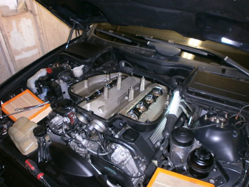
First off, its plenum off, along with airboxes top and bottom.
![Image]()
Its also a good idea to remove your 2 thermostat hoses, and the top hose from the radiator side. Also remove your viscous fan, a reverse thread 32mm spanner, and the fan cowling and expansion tank. Be careful as youw ill lose some coolant from the expansion tank. I syringed as much out as I could to minimise this. Also be aware of the small hose running from the expansion cap to the small plastic elbow on the top of the rad. Don’t snap it off!!! Store this all out of your way, you don’t want clutter
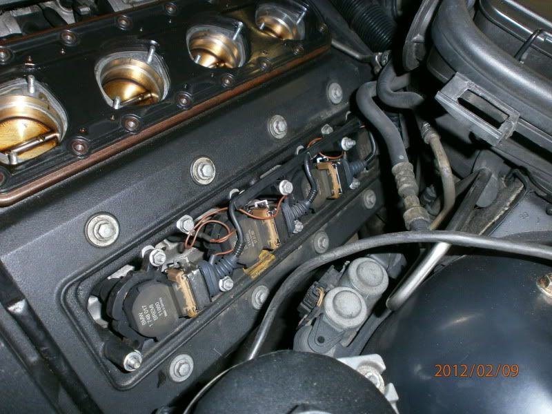
Then, remove your small coil pack covers and remove the coils and associated wiring. Make a note of any earth wire locations etc
![Image]()
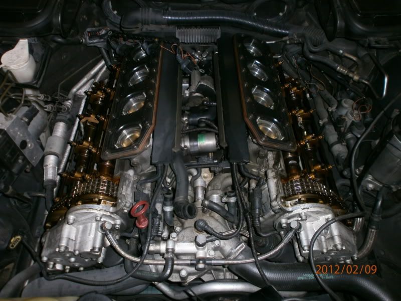
Next, remove the valve covers and store them safely, take car with the gaskets on them, remove the plugs
![Image]()
Now remove the 4 oil lines that cover the cams, 5 bolts on each. DO NOT MIX THESE UP
![Image]()
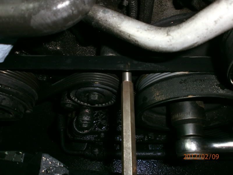
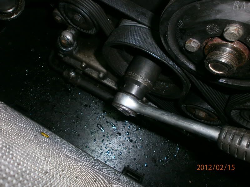
Now, rotate the engine on the crank pulley, 32mm socket, around to TDC firing position cylinder 1. Both intake and exhaust valves are closed at this point, and lock the engine with an 8.5mm drill with tape wrapped around it as shown in Raikku’s cam timing thread. I had made a locking pin in work, so I used this instead
![Image]()
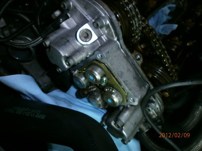
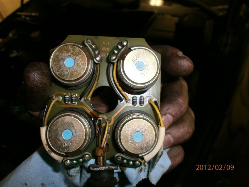
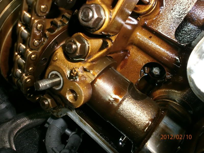
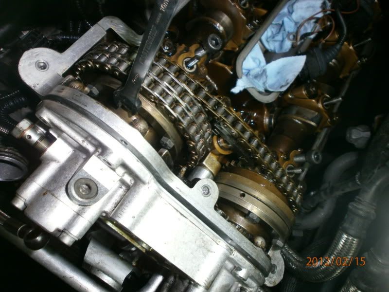
TIS says we need to put the cams into initial position next, and in absence of the special compressed air tool that the dealers have, we can release the pressure in the system by removing the solenoids. All the better as I had planned to renew the o rings on these anyways.
![Image]()
![Image]()
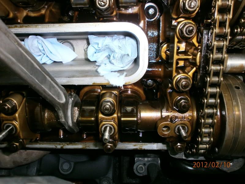
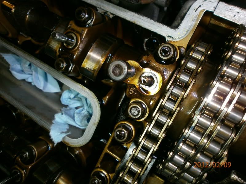
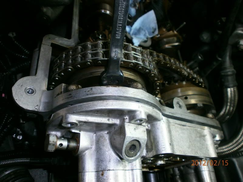
Now you can use a machined 27mm open ended spanner on the cast hex portion of the cams and move them to initial position.
![Image]()
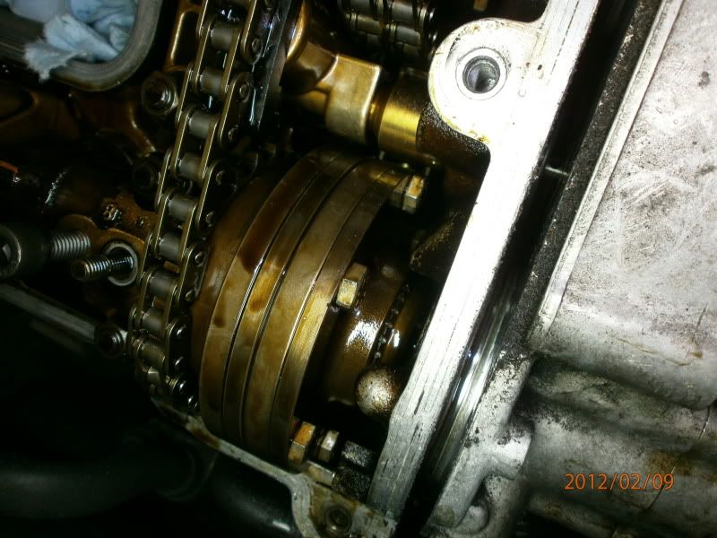
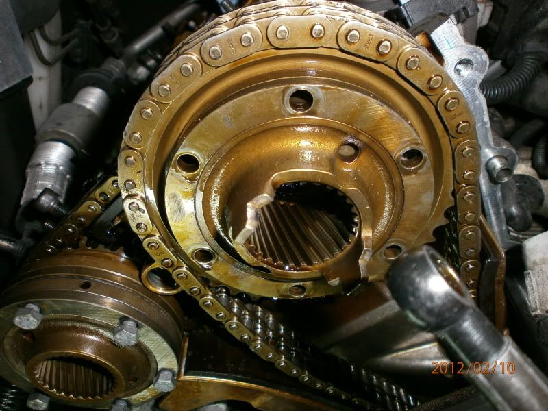
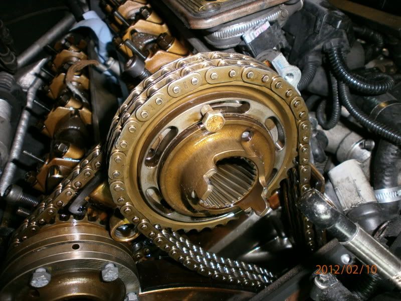
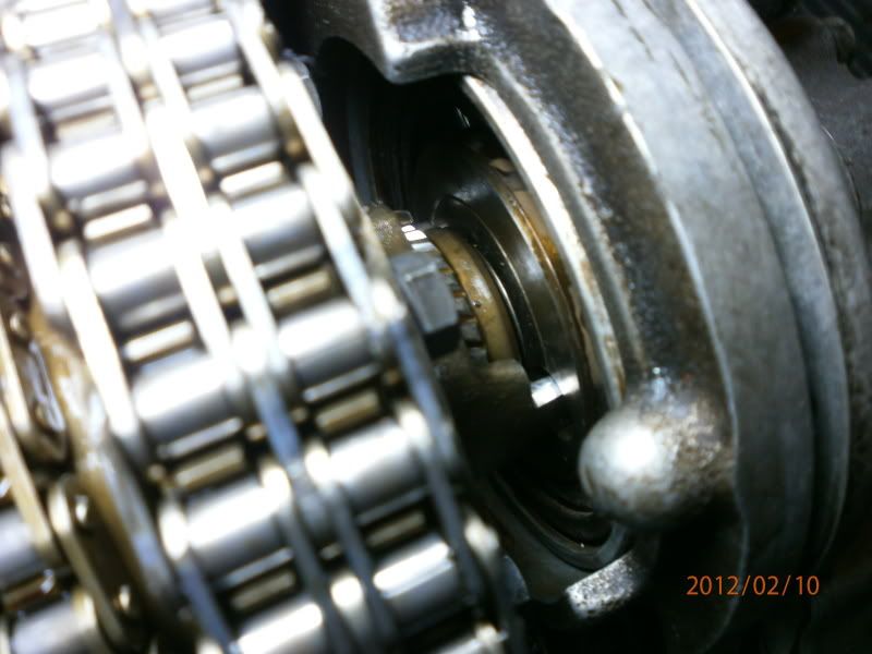
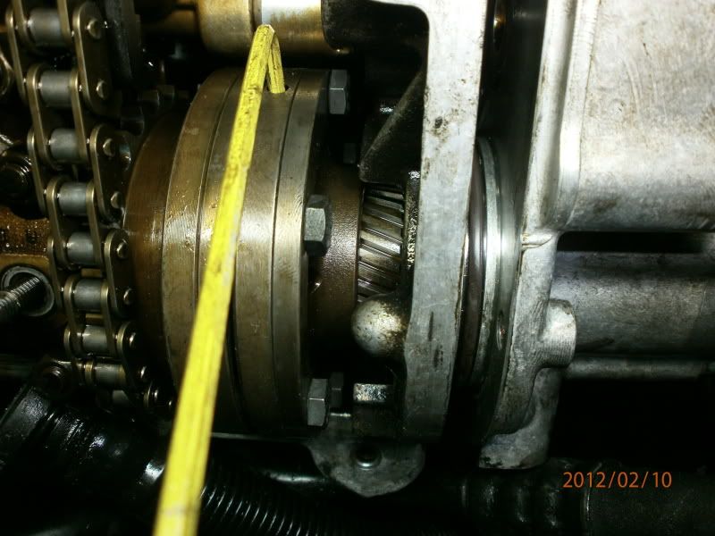
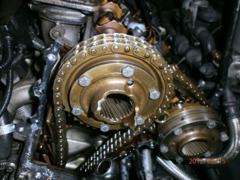
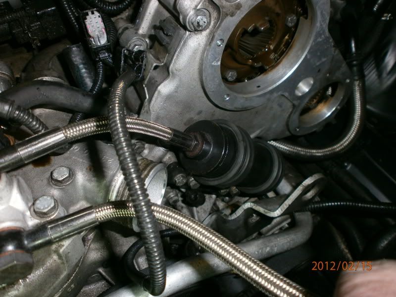
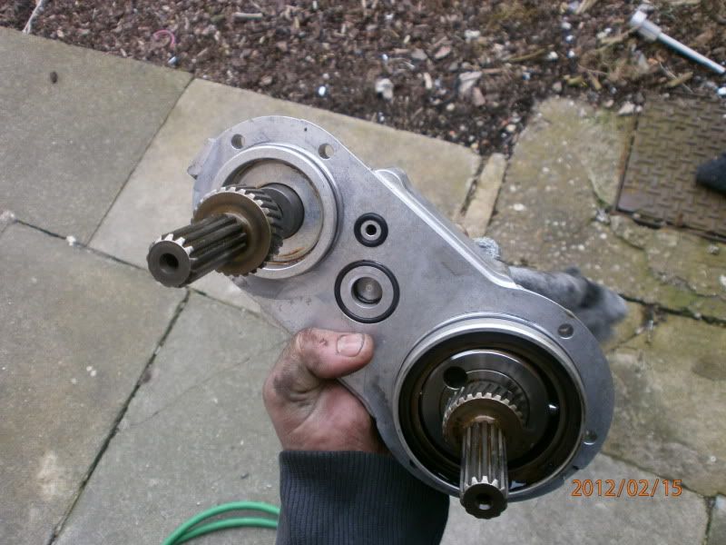
Once the cams are in the initial position, you will feel them come to a hard stop, as the vanos piston/helical gear comes to the end of its travel outwards from the cam. If you don’t feel this hard stop you can move the cam backwards and forwards until you hear it. In its initial position you should be somewhere like this. Note the position of the helical gear, just protruding from the helical hub. (take no notice that the vanos unit is unbolted, I have no picture of the helical gears in initial position with the vanos still bolted up)
![Image]()
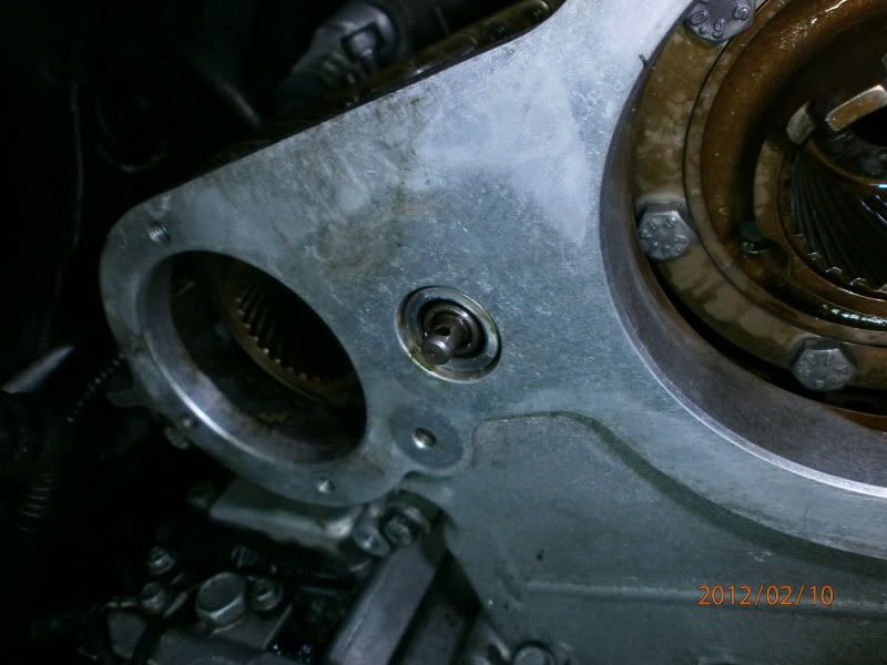
If you’re not sure, you can remove the piston cover and check to see if the piston is all the way back, it should be about 2mm from flush with the end of the bore.
![Image]()
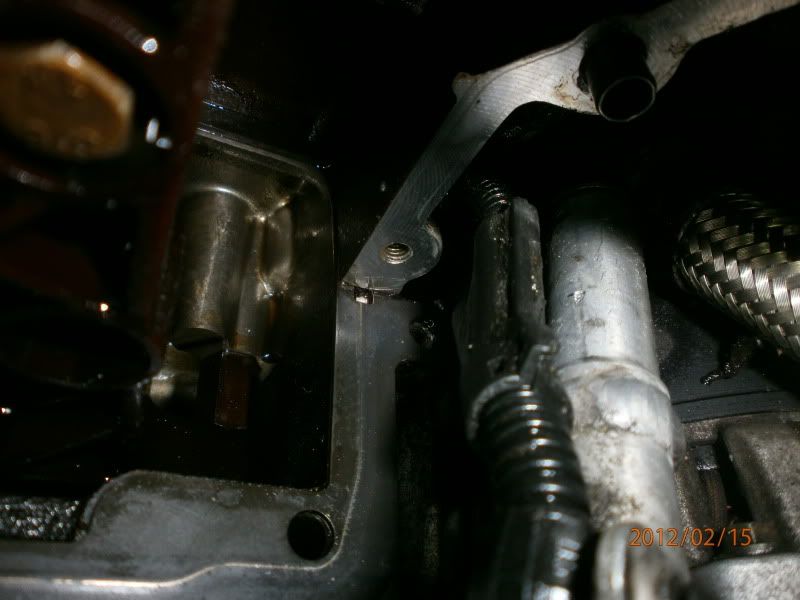
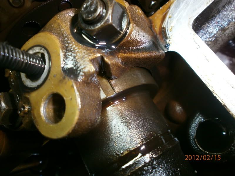
Also, assuming you r cam timing isn’t off, you should also see the cam timing marks align with the cut out in the cast as shown
![Image]()
![Image]()
![Image]()
Now remove the crank locking pin and crank the engine over 1 revolution to overlap TDC and insert your crank pin again.
Now, slacken the 3 visible hub retaining bolts on each of the cams
Remove the crank locking pin and crank the engine over 1 revolution to firing position TDC and insert your crank pin again.
Now slacken the remaining 3 visible bolts on each of the cams.
IMPORTANT: I noticed that on the above step, I could only access 2 of the bolts, not 3 on the exhaust cam when the engine was at TDC. Perhaps it was the casting of my components, who knows, but it happened to me. I had to just be aware and be a little cute in making sure the inaccessible bolt was already pre-undone by the time I cranked to TDC firing position in order to have all 6 bolts slack. If this happens to you, you’ll have to pre slacken that bolt first as you are cranking the engine around and it becomes accessible.
Also, make sure you slacken those bolts right off, as if you only do it a turn or so, when you slacken the opposite 3 off, the first 3 will bite up again and cause you a little trouble you could do without.
Now put in your 8mm drill bit or bolt and lock the cams. You may have to wiggle the cams a little using your 27mm spanner, but they should drop in, right where your timing marks line up
![Image]()
![Image]()
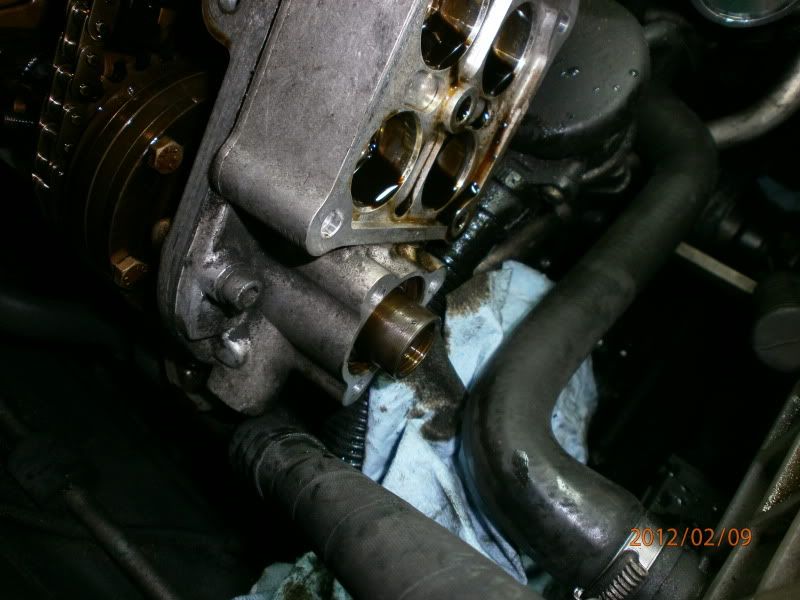
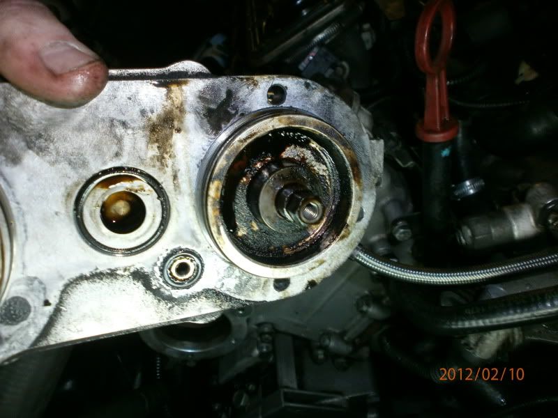
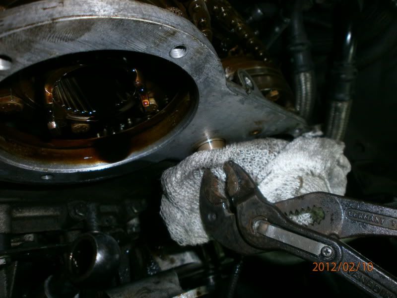
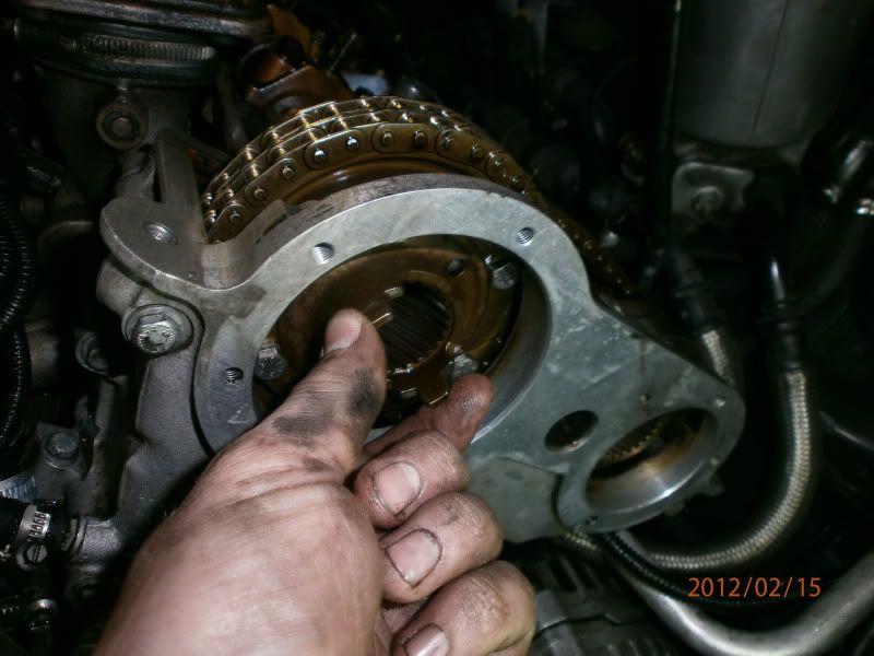
Now, undo your vanos unit mounting bolts, and pry the unit out. There are 2 indents one left and one right on the unit.
Now here’s where TIS is a little confusing. It says here, you should be able to just pull the unit off. However, with the cams locked, the helical gears won’t spit out of the helical hub. At the time I didn’t know this, and so I ended up unscrewing the vanos pistons from the helical gears to remove the unit, using a 7mm and 10mm spanner. These threads are left hand/CCW threads.
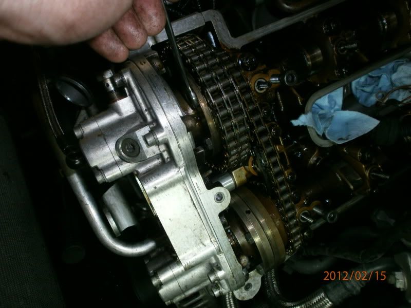
You can see from the next picture that this meant I could extract the unit. However, to get the helical gears out, or to remove it all as one unit complete with the helical gears, you should remove your cam locking pins, and whilst pulling on the unit, move your cam back and forth a little using your 27mm spanner, and the gears will spit right out, whilst still attached to the vanos unit.
![Image]()
Also remove your filter unit carefully using pliers wrapped in a rag or such ( filter removed in the above photo, the hole in the centre of the 2 large cam “holes” is where it lives
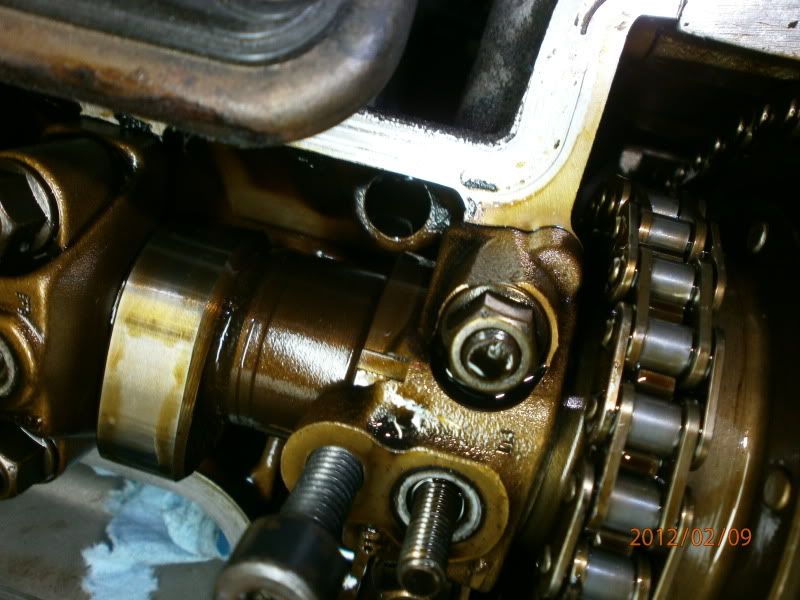
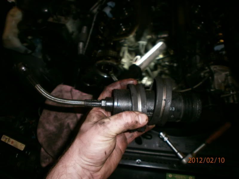
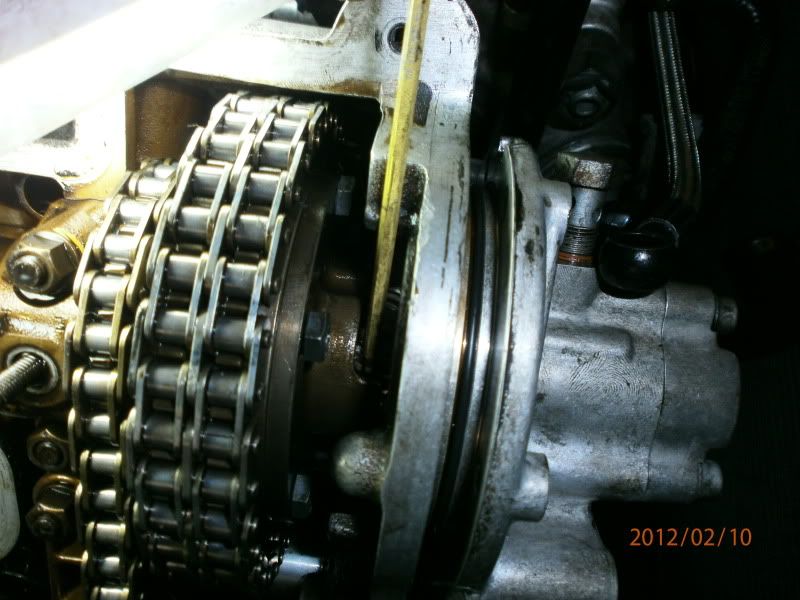
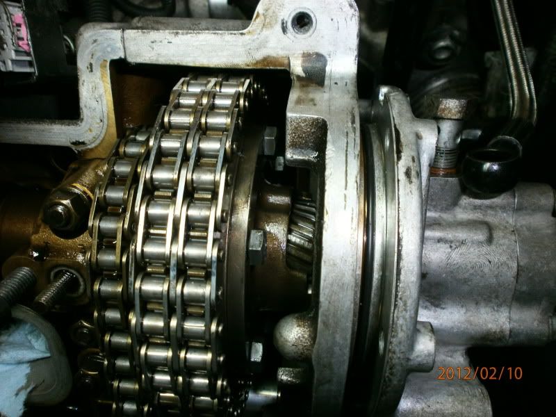
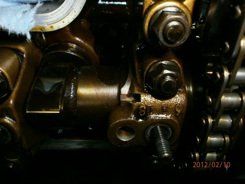
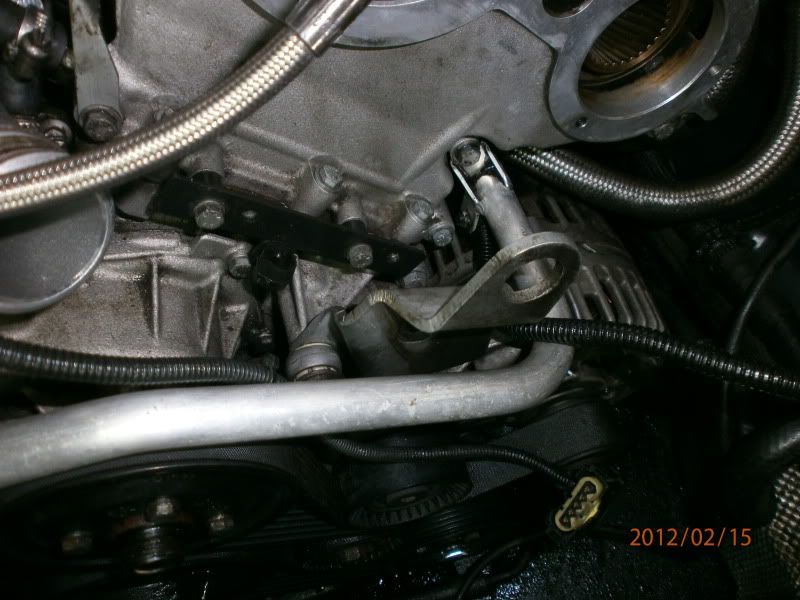
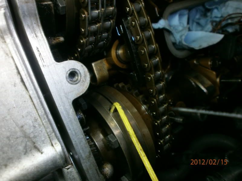
Next, remove your main chain tensioner piston. It lives screwed through the top timing cover, and pushes against the long deflection rail you can see in the next couple of pics, to give you an exact idea of its location. It’s a 20 or 21mm socket that fits over it and it screws right out.
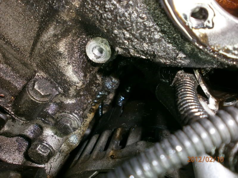
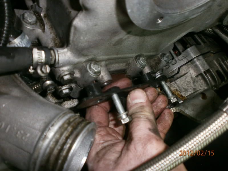
Remove your Vanos pressure accumulator to have better access at getting your Secondary air system piping out of the way. Its 2 10mm hex head bolts
![Image]()
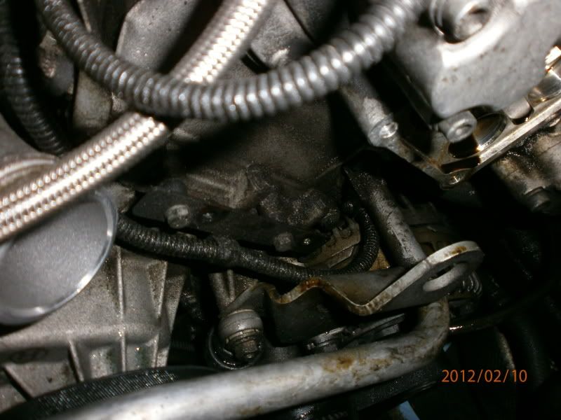
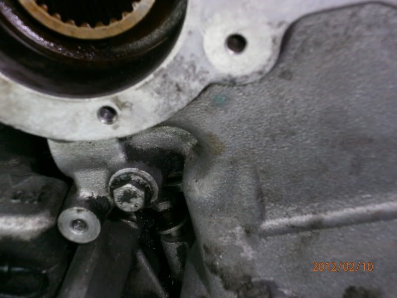
And it lives here
![Image]()
Not sure if all M5’s are the same for this as there were a number of changes to the accumulator system throughout production, but if its there, remove it for access
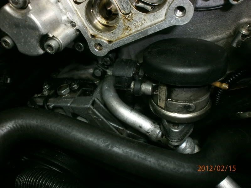
Remove your Secondary air system pipe and the flexi “vacuum hose” from the check valve. Its one bolt into each of the top timing covers, one either side. You can swing it out of your way then to get at all of the timing cover bolts
![Image]()
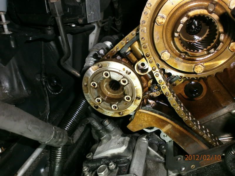
To remove the top timing cover, its 11 bolts, 5 around the base of the cover screwing vertically down into the lower cover, and 6 screwing horizontally into the cylinder head. There is one particular bolts that’s a total pain to see and undo, its one that screws vertically down and is located right in the corner near the A/C pump. You need patience and a good 10mm ring spanner to undo it 1 flat at a time
![Image]()
![Image]()
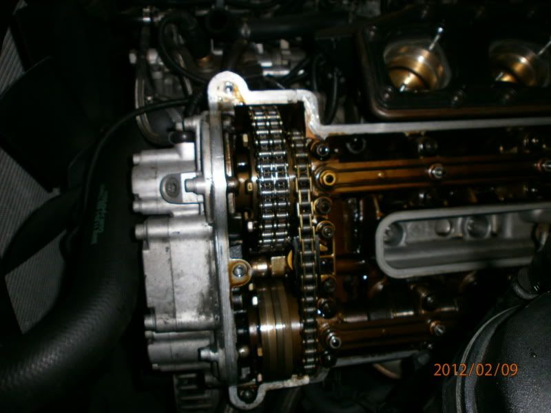
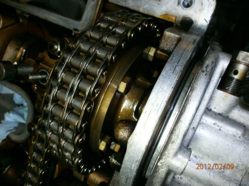
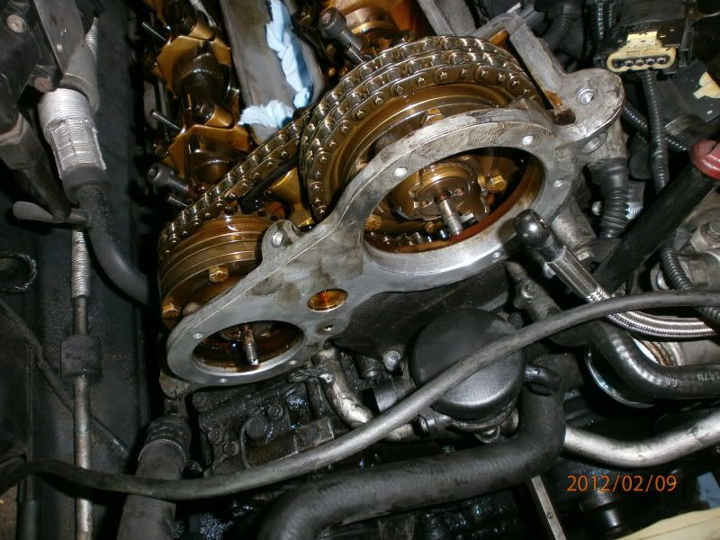
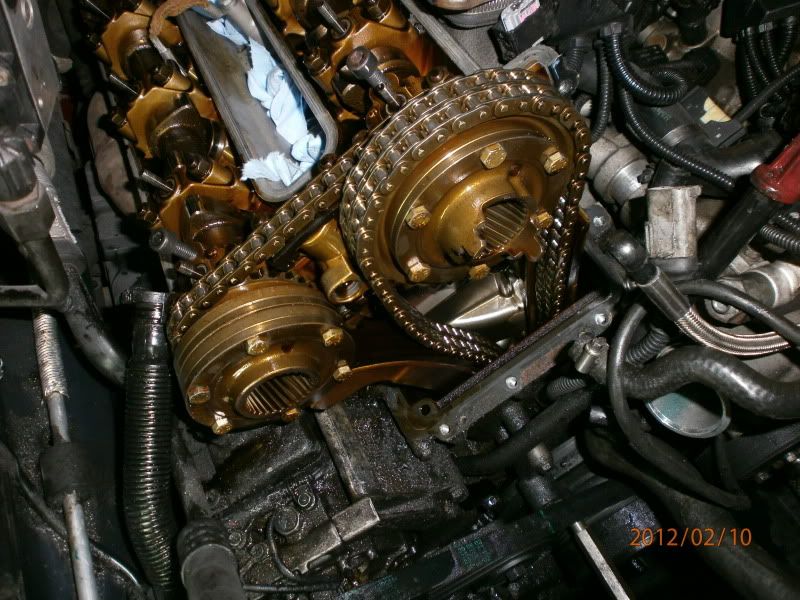
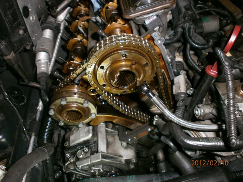
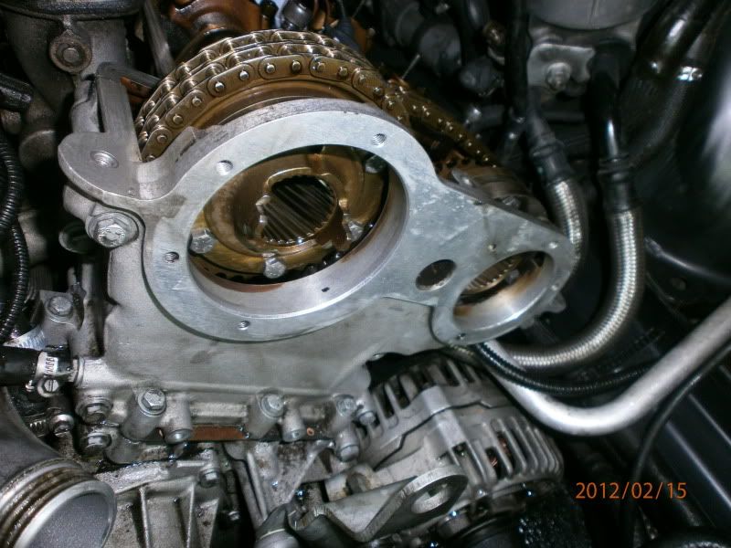
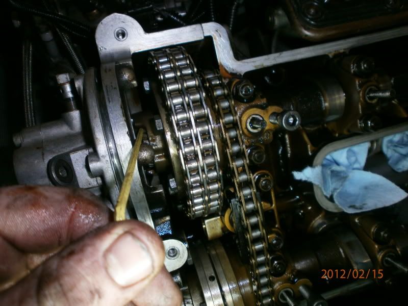
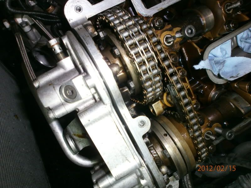
With the top cover off you’ll be greeted with this site, notice I have now been able to remove my helical gears since I unlocked my cams and “spat” the gears out. Once I did this I re locked the cams with my M8 bolts
You can see here the deflection guide I am on about on the left of the chain that is pushed against the chain by the tensioning piston
![Image]()
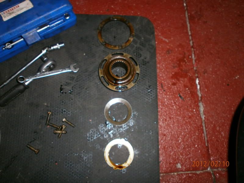
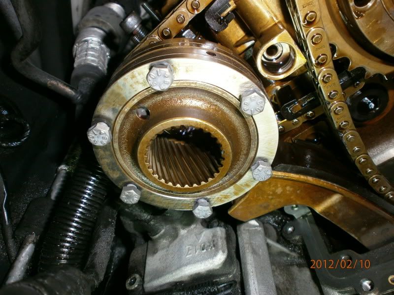
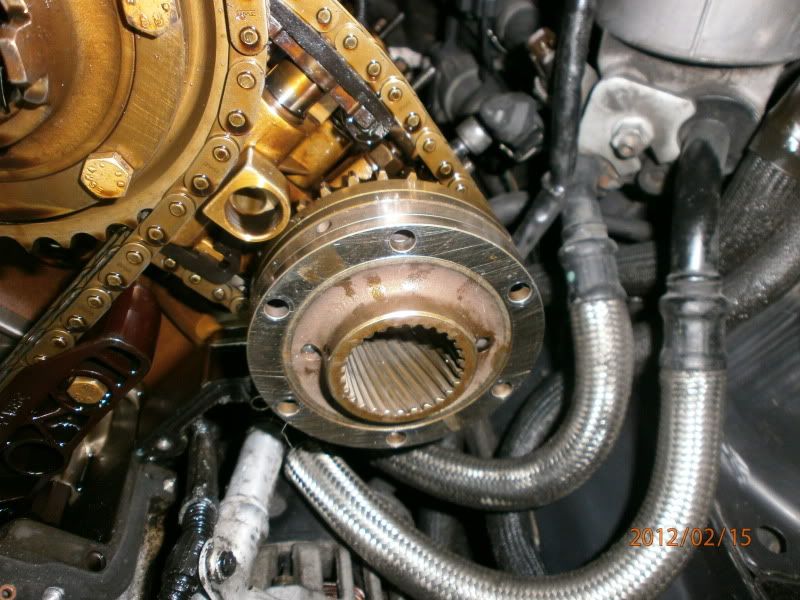
Now you can finally get to what we want to replace, the spacer rings. Remove the 6 bolts on each of the hubs on the cams. Note the orientation of the plates and particularly the 2 radial pump drive dogs on the inlet cam so you can install them in roughly the same position
![Image]()
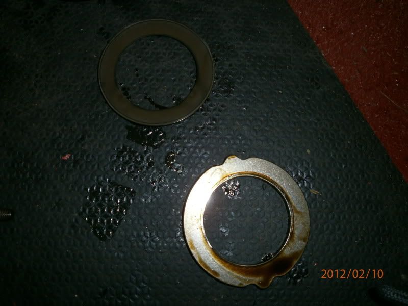
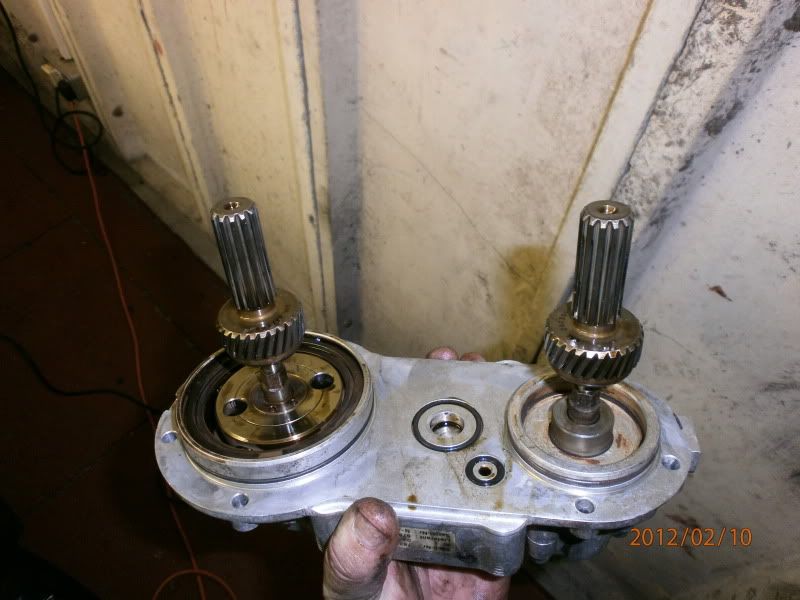
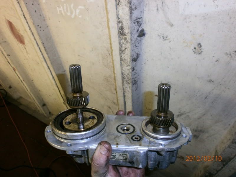
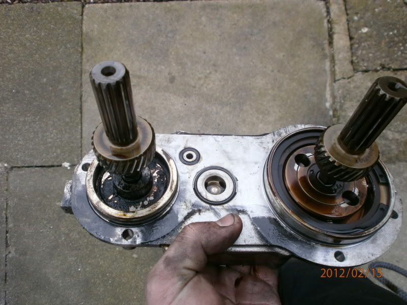
This is what you’ll remove top to bottom.
![Image]()
![Image]()
Note how the cup washer, 3<sup>rd</sup> down in the top pic, is concave as you look at it. When you put the new style (post 09/01) cup washer and plate in, this will be the opposite way around, so the small diameter of the washer presses against the hub above it on assembly. Therefore it will look convex as you lay it out as above.
Clean off the ring and hub assembly, smear some engine oil on your hub and new spring set, then install the new vanos spring cup washer into the hub so that the small diameter of the washer is in contact with the hub. Now fit the supporting ring making sure it sits in its small cutouts, it only fits in one way, you’ll see when you do it.
Clean everything up and reinstall using new 10.9 rated bolts, in the correct orientation, the new parts, up to just finger tight
![Image]()
![Image]()
Now do the same for the other cam
![Image]()
Now’s a good time to clean up your vanos units. Mine was crusty with gunk, a real shame, and so an attack with rags and brake cleaner sorted it out, from this
![Image]()
To this
![Image]()
Replace the 2 o rings on the face of the unit and use a little oil/grease to hold them in if they want to wiggle out. Push the pistons all the way in. You can see here the exhaust piston in, and the inlet piston out.
![Image]()
In reality this probably doesn’t matter so much as its likely the pistons will push all the way back to their initial positions anyway on reinstallation, but it pays to be methodical.
Now, reinstall your top timing cover.
PLEASE NOTE: you MUST have the bolt in the front bottom right of the cover that screws into the head horizontally already in the hole, or you can’t fit it afterwards
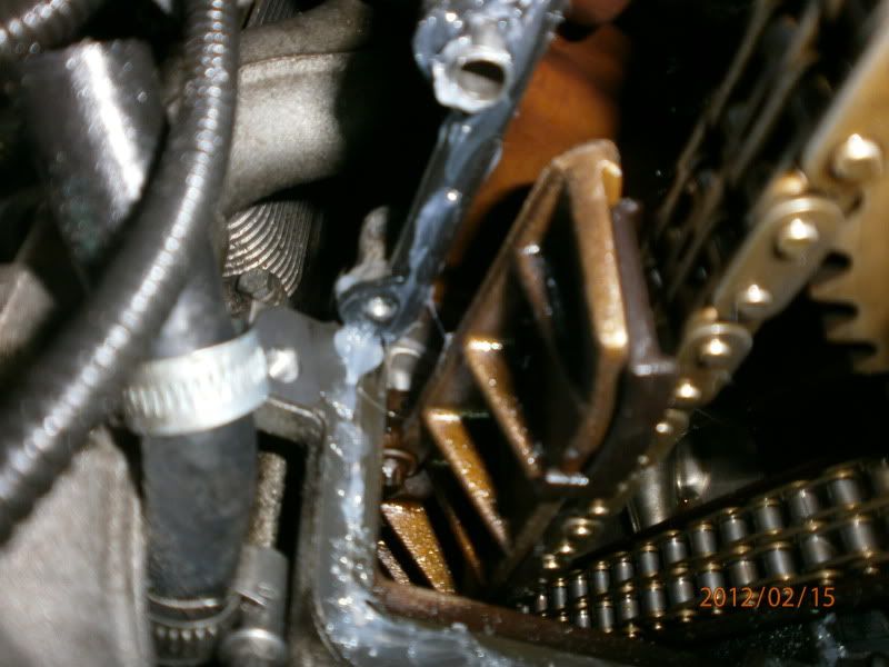
Clean all remnants of old gasket from the faces to be sealed. Be aware of the gaskets. Replace them and also you need a small amount of gasket sealer in the bottom corners where the top and bottom timing covers meet the head, you can see the cutout in the corner here. I know it’s the opposite bank, but I forgot to take a picture on the first bank, this gives you an idea. Personally I like to use s mall smear of the paste all along the sealing face to make sure I have a nice oil tight engine, but its up to you.
![Image]()
You’ll have to manipulate the timing tensioner rail to get the cover on. You can do this by inserting a screwdriver between the 2 cam hubs and moving it in the direction it would be pushed by the tensioner. Perhaps have a little play first before settling all of your gaskets etc
Reinstall your filter unit, give it a nice push so its home
![Image]()
Before we reinstall the vanos unit, we have to turn both of our splined hubs all the way clockwise on their adjustment slots, so that when we install the vanos the splined gears will rotate them back anticlockwise as we push the unit home.
I’ve just shown here in a picture for illustration what I mean.
![Image]()
You can see here the hub has been rotated clockwise up until the bolt reaches the end of its slot and cannot travel further. Do this for both hubs
Now we can offer up the vanos unit to the timing cover. First give the large o rings a coating of clean oil. Make sure the radial pump dimples are in the correct relation to the pegs on the inlet cam hub to pick up and then we can slide the unit on.
You may have to turn the vanos helical gear slightly to get the long straight part of the gear to engage. Once they do slide the unit up until the helical gear is just about to engage the splined hub.
Remember I said line the radial pump dimples up? Well if you’ve done it right, it should now look like this
![Image]()
At this point the helical gears may not want to mesh into the hub as they are ever so slightly out of line. If this is the case, we need to rotate the splined hub counter clockwise until it engages. Please note that you are only going to be a fraction of a tooth out, and it must engage in the first possible point it can. Don’t be tempted to think you can turn it a few teeth, this is wrong.
BMW have a special tool for this surprise surprise, but I found it simple enough with a 3mm Allen Key
![Image]()
If you apply gentle pressure to try and push the vanos unit on, whilst moving the splined hub gently counter clockwise you should feel it start to engage
Now do the same for the inlet cam
![Image]()
![Image]()
Once they are both in line and have just started to engage we can then push the vanos unit on until the 2 large O rings are just touching the timing cover, not all of the way home yet.
Now, run 2 of the vanos mounting bolts up finger tight, just to keep the unit there, not to push it home
Now, tighten the 3 visible hub screws on each cam to 10Nm, then slacken them off again about ¼ to ½ a turn.
Now install all of the vanos mounting bolts and tighten them down in ½ turn increments to make sure the unit is pulled in square.
Now reinstall your chain tensioner.
Take out your Crank locking pin and rotate the engine AGAINST its direction of travel until you feel a noticeable resistance. Now rotate the engine back to TDC and insert your crank locking pin.
This is simply to compensate for play in the vanos and means that now you can set the timing correctly, kind of like how you would make sure the slack of your riming chain was on one side of the engine when timing up an old car.
Now, retighten the 3 bolts on each splined hub. Remove your crank pin and your cam locking pins/bolts and rotate the engine 1 full revolution to overlap TDC, and re insert your crank pin.
Now tighten up your remaining 3 bolts on each hub.
Again remove the pin and rotate the engine 1 full turn to firing TDC. Re insert your crank pin.
Now, using your 27mm spanner, move the cams to their initial positions again as described above and check your timing marks. You should be spot on
![Image]()
![Image]()
* IF your timing is out rather than explain the process here, I’ll write an addendum at the end of the post to resolve this, see this step before going any further
Now, bank 1 is complete, its onto bank 2. I won’t go into masses of detail here, as essentially it’s the same job again, albeit ever so slightly different as you don’t have the main chain tensioner to worry about.
Stick with me though, as there may be a few tips or differences that help you with reassembling everything not applicable to bank 1
So, crank locked at TDC, cams in initial position, my timing looked slightly off from factory here. Not unusual from what I have heard from Raikku
![Image]()
Rotate engine to overlap TDC, slacken 6 visible bolts, crank back to firing TDC and lock crank, slacken 6 remaining bolts and rotate cams to correct position, insert cam pins
Undo vanos mounting bolts and pull vanos out. When the unit stops, remove your cam pins and the pull the unit off complete this time, whist rotating your cams with the 27mm spanner. Voila!!! The units come out complete this time. Relock your cams in the correct position.
Remove your filter carefully
![Image]()
Now remove the timing cover. Note there are 12 bolts, not 11 on this bank, one more screwing in from the front of the cover on the right hand side, so don’t try and lever it off after removing 11 bolts!!
Remember the really awkward bolt on bank 1?? Well, the mirrored bolt on this side is a little awkward too, but nowhere near as bad as bank 1. Patience is the key
![Image]()
Now remove your splined hubs and replace the vanos spring assemblies. Remember the correct orientation of the spring washer!!
![Image]()
![Image]()
Gaskets on and a smear of gasket paste for me before reinstalling the timing cover.
![Image]()
Timing cover on. I noticed I could manoeuvre the cover into position easier if I removed the accumulator bracket first
![Image]()
![Image]()
And then reinstall
![Image]()
Rotate hubs all the way clockwise
![Image]()
Remount the accumulator and Secondary air pump pipe and check valve, so you aren’t struggling under the vanos unit when its reinstalled
![Image]()
Clean a very cruddy vanos unit
![Image]()
![Image]()
Reinstall the unit as per above, and align radial pump, and helical gears
![Image]()
![Image]()
![Image]()
Tighten and then loosen the 3 visible hub bolts
![Image]()
![Image]()
Then install the vanos all the way home
Take out the play in the vanos as per above by removing crank and cam pins, rotating the engine backwards against direction of travel until resistance is felt, then back again to TDC
![Image]()
All locks back in and tighten the 3 visible bolts per hub
![Image]()
Locks out, crank to overlap, tighten the remaining 3 bolts per hub, rotate back to firing TDC and reinsert crank pin
Check your timing
![Image]()
All done
Refit your valve covers and all ancillaries.
I also renewed my Vanos o rings at the same time but there are other write ups about that so I shall leave that there
Once started my vanos made an initial rattle for a few seconds coupled with a lumpy idle, however this quietened down after say 5 seconds and the idle smoothed right out.
Presumably, this was because the cams were in the among position for startup, coupled with air in the vanos.
Anyway, fire away with questions and comments, I hope this guide will be of some use to you guys
*If for some reason your timing is still slightly out, you’ll have to make sure the cams are in the initial position. Remove your crank and cam pins and rotate engine to overlap TDC, slacken the 3 hub bolts on each hub.
Rotate the engine back to firing TDC and insert the crank pin. Undo the remaining 3 bolts per hub and using the 27mm spanner, rotate the cams until your groove and marks on the cams and bearing caps are aligned and slip your cam locking pins/bolts in.
Now retighten the 3 visible bolts per hub. Remove crank and cam pins and rotate to overlap TDC. Tighten the 3 remaining hub bolts and rotate back to firing TDC. Check the timing again as above with the cams in the initial position, the grooves should now be aligned
Its these people that help to make this board what it is, and give power to owners to get to know their Beast a little more, whilst saving some cash, improving their car, and getting some self satisfaction from accomplishing what perhaps they never thought they could do.
Raikku, for all of his DIY’s of which some relate to this job, for his support to other members and willingness to help whenever, wherever possible/
68FB, who has tackled this job also and explained a few things along the way.
M5Daemon, who gave me a gentle nudge in the right direction when I had a couple of headscratching moments.
And anyone else who gave me the time of day to help me get this job done.
I’d also like to say quickly that this isn’t a thread designed to steal anyone’s thunder, we all know who the pioneers of jobs like this are on the board. Rather there are members like those above who are extremely busy, and can’t write down and document every single job they do for the good of the community. Hopefully, this is where I can come in to try and do my part at giving something back
Right, so the thanks are over, we’ll start at the beginning. I have a MY2000 built in February 2000, meaning not only are my vanos spring plates 12 years old, but they are also the old, thinner, inverted type. My units were not exceptionally noisy, and if anything were pretty much silent at cold start, but once the car warmed up I did get the tell tale grumble that pretty much all cars seem to have after a few years and miles.
I have always wanted to “get to know” parts of the vanos system, and also wanted to check out my cam timing, and whilst the solenoids were out, put fresh o rings on them and clean up or discard the old filters in there. What better time to spend an extra £90 and put a set of spring plates in there for good measure? Furthermore, although a few people have carried this job out, its not documented as a step by step on the board for all to see. Although the knowledge is out there, I thought it would be nice to have a dedicated thread about it.
If there are any parts of this thread that people would like changing as they feel something is missed out or not explained properly, then please let me know. Likewise if you think some steps could be skipped or are plain wrong in your eyes, I’m all ears.
So enough with the intro’s lets get to it.
First off, its plenum off, along with airboxes top and bottom.
Its also a good idea to remove your 2 thermostat hoses, and the top hose from the radiator side. Also remove your viscous fan, a reverse thread 32mm spanner, and the fan cowling and expansion tank. Be careful as youw ill lose some coolant from the expansion tank. I syringed as much out as I could to minimise this. Also be aware of the small hose running from the expansion cap to the small plastic elbow on the top of the rad. Don’t snap it off!!! Store this all out of your way, you don’t want clutter
Then, remove your small coil pack covers and remove the coils and associated wiring. Make a note of any earth wire locations etc
Next, remove the valve covers and store them safely, take car with the gaskets on them, remove the plugs
Now remove the 4 oil lines that cover the cams, 5 bolts on each. DO NOT MIX THESE UP
Now, rotate the engine on the crank pulley, 32mm socket, around to TDC firing position cylinder 1. Both intake and exhaust valves are closed at this point, and lock the engine with an 8.5mm drill with tape wrapped around it as shown in Raikku’s cam timing thread. I had made a locking pin in work, so I used this instead
TIS says we need to put the cams into initial position next, and in absence of the special compressed air tool that the dealers have, we can release the pressure in the system by removing the solenoids. All the better as I had planned to renew the o rings on these anyways.
Now you can use a machined 27mm open ended spanner on the cast hex portion of the cams and move them to initial position.
Once the cams are in the initial position, you will feel them come to a hard stop, as the vanos piston/helical gear comes to the end of its travel outwards from the cam. If you don’t feel this hard stop you can move the cam backwards and forwards until you hear it. In its initial position you should be somewhere like this. Note the position of the helical gear, just protruding from the helical hub. (take no notice that the vanos unit is unbolted, I have no picture of the helical gears in initial position with the vanos still bolted up)
If you’re not sure, you can remove the piston cover and check to see if the piston is all the way back, it should be about 2mm from flush with the end of the bore.
Also, assuming you r cam timing isn’t off, you should also see the cam timing marks align with the cut out in the cast as shown
Now remove the crank locking pin and crank the engine over 1 revolution to overlap TDC and insert your crank pin again.
Now, slacken the 3 visible hub retaining bolts on each of the cams
Remove the crank locking pin and crank the engine over 1 revolution to firing position TDC and insert your crank pin again.
Now slacken the remaining 3 visible bolts on each of the cams.
IMPORTANT: I noticed that on the above step, I could only access 2 of the bolts, not 3 on the exhaust cam when the engine was at TDC. Perhaps it was the casting of my components, who knows, but it happened to me. I had to just be aware and be a little cute in making sure the inaccessible bolt was already pre-undone by the time I cranked to TDC firing position in order to have all 6 bolts slack. If this happens to you, you’ll have to pre slacken that bolt first as you are cranking the engine around and it becomes accessible.
Also, make sure you slacken those bolts right off, as if you only do it a turn or so, when you slacken the opposite 3 off, the first 3 will bite up again and cause you a little trouble you could do without.
Now put in your 8mm drill bit or bolt and lock the cams. You may have to wiggle the cams a little using your 27mm spanner, but they should drop in, right where your timing marks line up
Now, undo your vanos unit mounting bolts, and pry the unit out. There are 2 indents one left and one right on the unit.
Now here’s where TIS is a little confusing. It says here, you should be able to just pull the unit off. However, with the cams locked, the helical gears won’t spit out of the helical hub. At the time I didn’t know this, and so I ended up unscrewing the vanos pistons from the helical gears to remove the unit, using a 7mm and 10mm spanner. These threads are left hand/CCW threads.
You can see from the next picture that this meant I could extract the unit. However, to get the helical gears out, or to remove it all as one unit complete with the helical gears, you should remove your cam locking pins, and whilst pulling on the unit, move your cam back and forth a little using your 27mm spanner, and the gears will spit right out, whilst still attached to the vanos unit.
Also remove your filter unit carefully using pliers wrapped in a rag or such ( filter removed in the above photo, the hole in the centre of the 2 large cam “holes” is where it lives
Next, remove your main chain tensioner piston. It lives screwed through the top timing cover, and pushes against the long deflection rail you can see in the next couple of pics, to give you an exact idea of its location. It’s a 20 or 21mm socket that fits over it and it screws right out.
Remove your Vanos pressure accumulator to have better access at getting your Secondary air system piping out of the way. Its 2 10mm hex head bolts
And it lives here
Not sure if all M5’s are the same for this as there were a number of changes to the accumulator system throughout production, but if its there, remove it for access
Remove your Secondary air system pipe and the flexi “vacuum hose” from the check valve. Its one bolt into each of the top timing covers, one either side. You can swing it out of your way then to get at all of the timing cover bolts
To remove the top timing cover, its 11 bolts, 5 around the base of the cover screwing vertically down into the lower cover, and 6 screwing horizontally into the cylinder head. There is one particular bolts that’s a total pain to see and undo, its one that screws vertically down and is located right in the corner near the A/C pump. You need patience and a good 10mm ring spanner to undo it 1 flat at a time

With the top cover off you’ll be greeted with this site, notice I have now been able to remove my helical gears since I unlocked my cams and “spat” the gears out. Once I did this I re locked the cams with my M8 bolts
You can see here the deflection guide I am on about on the left of the chain that is pushed against the chain by the tensioning piston
Now you can finally get to what we want to replace, the spacer rings. Remove the 6 bolts on each of the hubs on the cams. Note the orientation of the plates and particularly the 2 radial pump drive dogs on the inlet cam so you can install them in roughly the same position
This is what you’ll remove top to bottom.
Note how the cup washer, 3<sup>rd</sup> down in the top pic, is concave as you look at it. When you put the new style (post 09/01) cup washer and plate in, this will be the opposite way around, so the small diameter of the washer presses against the hub above it on assembly. Therefore it will look convex as you lay it out as above.
Clean off the ring and hub assembly, smear some engine oil on your hub and new spring set, then install the new vanos spring cup washer into the hub so that the small diameter of the washer is in contact with the hub. Now fit the supporting ring making sure it sits in its small cutouts, it only fits in one way, you’ll see when you do it.
Clean everything up and reinstall using new 10.9 rated bolts, in the correct orientation, the new parts, up to just finger tight
Now do the same for the other cam
Now’s a good time to clean up your vanos units. Mine was crusty with gunk, a real shame, and so an attack with rags and brake cleaner sorted it out, from this
To this
Replace the 2 o rings on the face of the unit and use a little oil/grease to hold them in if they want to wiggle out. Push the pistons all the way in. You can see here the exhaust piston in, and the inlet piston out.
In reality this probably doesn’t matter so much as its likely the pistons will push all the way back to their initial positions anyway on reinstallation, but it pays to be methodical.
Now, reinstall your top timing cover.
PLEASE NOTE: you MUST have the bolt in the front bottom right of the cover that screws into the head horizontally already in the hole, or you can’t fit it afterwards
Clean all remnants of old gasket from the faces to be sealed. Be aware of the gaskets. Replace them and also you need a small amount of gasket sealer in the bottom corners where the top and bottom timing covers meet the head, you can see the cutout in the corner here. I know it’s the opposite bank, but I forgot to take a picture on the first bank, this gives you an idea. Personally I like to use s mall smear of the paste all along the sealing face to make sure I have a nice oil tight engine, but its up to you.
You’ll have to manipulate the timing tensioner rail to get the cover on. You can do this by inserting a screwdriver between the 2 cam hubs and moving it in the direction it would be pushed by the tensioner. Perhaps have a little play first before settling all of your gaskets etc
Reinstall your filter unit, give it a nice push so its home
Before we reinstall the vanos unit, we have to turn both of our splined hubs all the way clockwise on their adjustment slots, so that when we install the vanos the splined gears will rotate them back anticlockwise as we push the unit home.
I’ve just shown here in a picture for illustration what I mean.
You can see here the hub has been rotated clockwise up until the bolt reaches the end of its slot and cannot travel further. Do this for both hubs
Now we can offer up the vanos unit to the timing cover. First give the large o rings a coating of clean oil. Make sure the radial pump dimples are in the correct relation to the pegs on the inlet cam hub to pick up and then we can slide the unit on.
You may have to turn the vanos helical gear slightly to get the long straight part of the gear to engage. Once they do slide the unit up until the helical gear is just about to engage the splined hub.
Remember I said line the radial pump dimples up? Well if you’ve done it right, it should now look like this
At this point the helical gears may not want to mesh into the hub as they are ever so slightly out of line. If this is the case, we need to rotate the splined hub counter clockwise until it engages. Please note that you are only going to be a fraction of a tooth out, and it must engage in the first possible point it can. Don’t be tempted to think you can turn it a few teeth, this is wrong.
BMW have a special tool for this surprise surprise, but I found it simple enough with a 3mm Allen Key
If you apply gentle pressure to try and push the vanos unit on, whilst moving the splined hub gently counter clockwise you should feel it start to engage
Now do the same for the inlet cam
Once they are both in line and have just started to engage we can then push the vanos unit on until the 2 large O rings are just touching the timing cover, not all of the way home yet.
Now, run 2 of the vanos mounting bolts up finger tight, just to keep the unit there, not to push it home
Now, tighten the 3 visible hub screws on each cam to 10Nm, then slacken them off again about ¼ to ½ a turn.
Now install all of the vanos mounting bolts and tighten them down in ½ turn increments to make sure the unit is pulled in square.
Now reinstall your chain tensioner.
Take out your Crank locking pin and rotate the engine AGAINST its direction of travel until you feel a noticeable resistance. Now rotate the engine back to TDC and insert your crank locking pin.
This is simply to compensate for play in the vanos and means that now you can set the timing correctly, kind of like how you would make sure the slack of your riming chain was on one side of the engine when timing up an old car.
Now, retighten the 3 bolts on each splined hub. Remove your crank pin and your cam locking pins/bolts and rotate the engine 1 full revolution to overlap TDC, and re insert your crank pin.
Now tighten up your remaining 3 bolts on each hub.
Again remove the pin and rotate the engine 1 full turn to firing TDC. Re insert your crank pin.
Now, using your 27mm spanner, move the cams to their initial positions again as described above and check your timing marks. You should be spot on
* IF your timing is out rather than explain the process here, I’ll write an addendum at the end of the post to resolve this, see this step before going any further
Now, bank 1 is complete, its onto bank 2. I won’t go into masses of detail here, as essentially it’s the same job again, albeit ever so slightly different as you don’t have the main chain tensioner to worry about.
Stick with me though, as there may be a few tips or differences that help you with reassembling everything not applicable to bank 1
So, crank locked at TDC, cams in initial position, my timing looked slightly off from factory here. Not unusual from what I have heard from Raikku
Rotate engine to overlap TDC, slacken 6 visible bolts, crank back to firing TDC and lock crank, slacken 6 remaining bolts and rotate cams to correct position, insert cam pins
Undo vanos mounting bolts and pull vanos out. When the unit stops, remove your cam pins and the pull the unit off complete this time, whist rotating your cams with the 27mm spanner. Voila!!! The units come out complete this time. Relock your cams in the correct position.
Remove your filter carefully
Now remove the timing cover. Note there are 12 bolts, not 11 on this bank, one more screwing in from the front of the cover on the right hand side, so don’t try and lever it off after removing 11 bolts!!
Remember the really awkward bolt on bank 1?? Well, the mirrored bolt on this side is a little awkward too, but nowhere near as bad as bank 1. Patience is the key
Now remove your splined hubs and replace the vanos spring assemblies. Remember the correct orientation of the spring washer!!
Gaskets on and a smear of gasket paste for me before reinstalling the timing cover.
Timing cover on. I noticed I could manoeuvre the cover into position easier if I removed the accumulator bracket first
And then reinstall
Rotate hubs all the way clockwise
Remount the accumulator and Secondary air pump pipe and check valve, so you aren’t struggling under the vanos unit when its reinstalled
Clean a very cruddy vanos unit
Reinstall the unit as per above, and align radial pump, and helical gears
Tighten and then loosen the 3 visible hub bolts
Then install the vanos all the way home
Take out the play in the vanos as per above by removing crank and cam pins, rotating the engine backwards against direction of travel until resistance is felt, then back again to TDC
All locks back in and tighten the 3 visible bolts per hub
Locks out, crank to overlap, tighten the remaining 3 bolts per hub, rotate back to firing TDC and reinsert crank pin
Check your timing
All done
Refit your valve covers and all ancillaries.
I also renewed my Vanos o rings at the same time but there are other write ups about that so I shall leave that there
Once started my vanos made an initial rattle for a few seconds coupled with a lumpy idle, however this quietened down after say 5 seconds and the idle smoothed right out.
Presumably, this was because the cams were in the among position for startup, coupled with air in the vanos.
Anyway, fire away with questions and comments, I hope this guide will be of some use to you guys
*If for some reason your timing is still slightly out, you’ll have to make sure the cams are in the initial position. Remove your crank and cam pins and rotate engine to overlap TDC, slacken the 3 hub bolts on each hub.
Rotate the engine back to firing TDC and insert the crank pin. Undo the remaining 3 bolts per hub and using the 27mm spanner, rotate the cams until your groove and marks on the cams and bearing caps are aligned and slip your cam locking pins/bolts in.
Now retighten the 3 visible bolts per hub. Remove crank and cam pins and rotate to overlap TDC. Tighten the 3 remaining hub bolts and rotate back to firing TDC. Check the timing again as above with the cams in the initial position, the grooves should now be aligned
")


